Over the last few weeks I have been thinking about the overall controller architecture, 3D printing some test Raspberry Pi cases, and updating the Python test software.
Plotter updates
Timed operations
After refactoring the giant single-file script from the previous post, I noticed the script was actually running very inefficiently, partly down to the fact that the 2D canvas had to redraw the whole robot on every frame, but also because of the way some of the threaded classes (e.g. input handler, serial handler) were inadvertently constantly interrupting the main thread, because they were relying on use of the root window’s after() method. The timing loops are cleaned up now and the code runs much more efficiently.
Here is an example I figured out, of how to create a class to run a function in a separate thread, with a defined time interval, that is pausable/stoppable. It subclasses the Thread class, and uses the help of an Event object to handle the timing functionality. After creating an object of this class, you call its start() method, which invokes the run() method in a separate thread. The pause(), resume() and stop() methods perform the respective actions. The example is a stripped-down version of an input handler, which applies the equations of motion to user inputs, as shown in a past post.
import threading
from time import time
import math
class InputHandlerExample(threading.Thread):
    def __init__(self):
        # Threading/timing vars
        threading.Thread.__init__(self)
        self.event = threading.Event()
        self.dt = 0.05  # 50 ms
        self.paused = False
        self.prevT = time()
        self.currT = time()
        self.target = 0.0
        self.speed = 0.0

        # Input vars
        self.inputNormalised = 0.0

    def run(self):
        while not self.event.isSet():
            if not self.paused:
                self.pollInputs()
            self.event.wait(self.dt)

    def pause(self):
        self.paused = True

    def resume(self):
        self.paused = False

    def stop(self):
        self.event.set()

    def pollInputs(self):
        # Upate current time
        self.currT = time()

        # Get user input somehow here, normalise value
        #self.inputNormalised = getInput()

        # Update target and speed
        self.target, self.speed = self.updateMotion(
            self.inputNormalised, self.target, self.speed)

        # Make use of the returned target and speed values
        #useResults(target, speed)

        # Update previous time
        self.prevT = self.currT

    def updateMotion(self, i, target, speed):
        m = 1.0
        u0 = speed

        # Force minus linear drag
        inputForceMax = 1000
        dragForceCoef = 5
        F = inputForceMax*i - dragForceCoef*u0
        a = F/m
        t = self.currT - self.prevT

        # Zero t if it's too large
        if t > 0.5:
            t = 0.0
        x0 = target

        # Equations of motion
        u = u0 + a*t
        x = x0 + u0*t + 0.5*a*math.pow(t, 2)

        return x, u
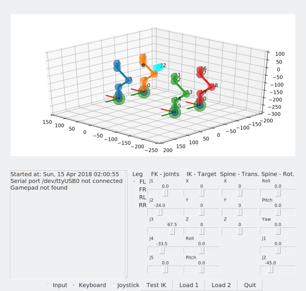
3d plot
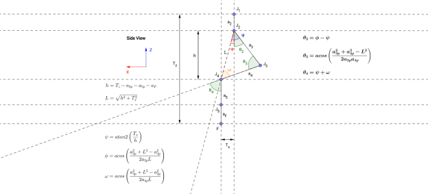
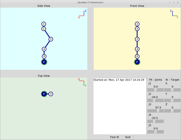
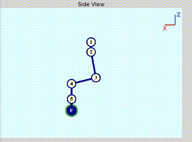
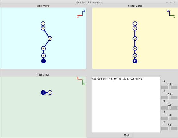
So far the 2D representation of the robot worked OK, but it has its limitations. So I finally decided to put some effort into updating the representation of the robot. I went with matplotlib and its 3D extensions with the mplot3d toolkit.
The joints are simply represented using the scatter() function, while the lines are simply drawn with plot(). The text() function overlays the number of the joints over the joint positions. The leg target widgets use a combination of the above functions. The 3D plot is updated using the FuncAnimation class.
Since this designed for Matlab-style plotting rather than a simulator, the performance is still somewhat lacking (not as fast as the 2D canvas), but I wanted to be able to get something working fairly quickly and not waste too much time with something like OpenGL, since my aim is to have a test program and not build a 3D simulator from scratch. There’s always ROS and Gazebo if I need to take this further!
As a side note, I have added the option in the main program to be able to select between 2D or 3D drawing mode, as well as no drawing, which should be useful for speeding up execution when running on the Raspberry Pi in headless mode (no screen).
Here is a screenshot and a video of the results:
Canvas redrawing
Another efficiency issue was the fact that previously the canvas was cleared an then redrawn from scratch on every frame update. To improve efficiency, both for the 2D and the 3D cases, the drawing classes now have structs to keep track of all element handles, and the redraw functions move the elements to their updated positions. For the 2D case (TkInter canvas), this is done with the coords() method. For the 3D case (matplotlib) it was a bit trickier, but I managed it with a combination of methods:
- For lines (plot): set_data() and set_3d_properties()
- For points (scatter): ._offsets3d = juggle_axes()
- For text overlay (text): set_position and set_3d_properties()
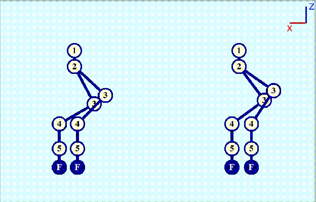
Updated class diagram
The interaction between the different elements is cleaned up and now looks like this:

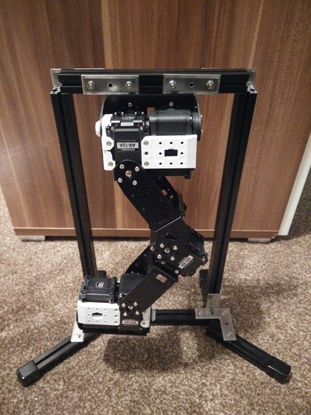
Hardware architecture
Now, to make a switch and talk a bit more about the hardware, here is the current plan of how all the components will probably look like:

I have in fact got two Raspberry Pis now, a Pi 3 Model B as well as a Pi Zero W. Both now have built-in WiFi, but I am going with the larger Pi 3 as the current choice for main controller, favouring the quad-core CPU over the Zero’s single core.
I tried 3D printing some cases from Thingiverse for each Pi, and here are the results. A great plus point of the Pi 3 case is that it has mounting points which will be easy to locate on the main robot body.


You can find my builds and their sources on Thingiverse: