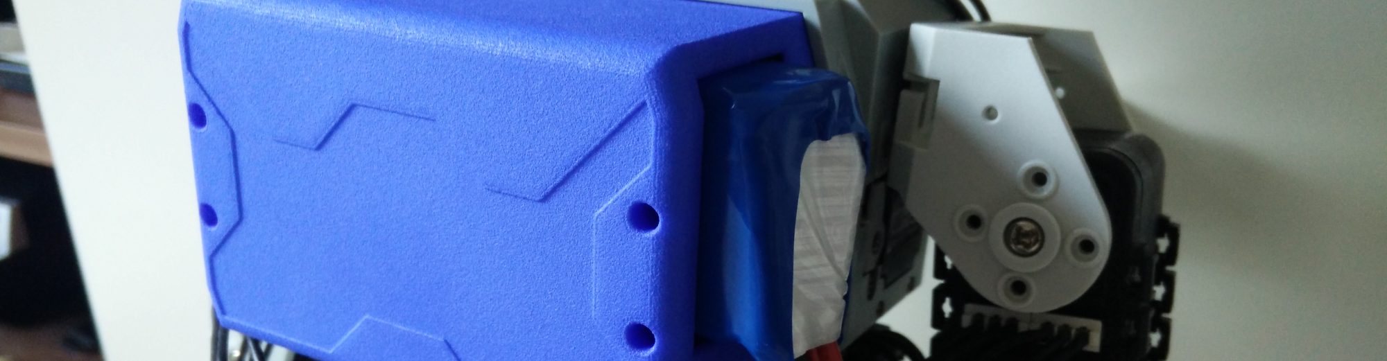
Most of the parts for the Bioloid’s power supply have now arrived. Here are some pictures of the Pi 2 being powered by the 11.1 V, 5500 mAh battery. The battery also powers the SMPS2Dynamixel adaptor for the Dynamixel servos. The step-down to 5 V for the Raspberry Pi is performed by a 3A UBEC (Universal Battery Elimination Circuit), which has a handy MicroUSB output. This seems to be the ideal way of powering the Pi, rather than e.g. via the powered hub or GPIO pins, which bypass the voltage protection, especially when considering that the Pi has to power the peripherals. The USB2AX for the servo control is powered via the Raspberry’s USB port, as will the A-Star MCU.
5500 mAh LiPo battery powering Raspberry Pi 2 and Robotis hardware.
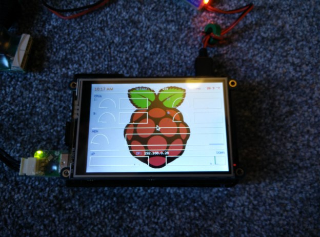
Conky running on Raspbian!
Raspberry Pi 2
The Pi is currently running Raspbian and now also has this great 480×320 touchscreen from Adafruit! I installed ROS Indigo from source using this guide. I have also added Conky on the desktop, a lightweight and fully customisable system monitor, as a way of directly visualising the Pi’s current status. The touchscreen feature of the screen will be of use in the future, if some simple GUI is made for the robot.
Hardware layout
The next picture shows the current hardware layout of the whole robot. As there is a lot to power, I went for the beefy 5500 mAh battery, but as it weighs 417 grams, I might have to eventually get something lighter for the robot to be able to carry, at the expense of a shorter run time.
In this post, I’ll be describing the first stage in getting a working representation of the, as of yet unnamed robot, into the ROS world. I will also be briefly exploring the MoveIt! library, as this might be a useful tool for the future.
The virtual representation of the Bioloid will be built using CAD models of all the individual servos and support brackets. The robot will be loaded up in RViz, where its links an joints will be manipulated. Inverse kinematics will hopefully be calculated by the MoveIt! package later on. But first, a definition is needed of how the joints and links are all connected, and how to move between their frames of reference. The individual CAD components will be oriented correctly onto these frames.
On a side note, I had the chance to photograph the Bioloid in its current state, and also had a Raspberry Pi 2 delivered!
The Bioloid, currently awaiting a heart and brain transplant.
Raspberry Pi 2 delivered! This may become the ROS brain in the near future.
After some background reading, I found out that the best way to create this representation in ROS is by using a standardised XML format file called the Unified Robot Description Format (URDF).
CAD models
In the past I had made a start on drawing a CAD model of the Robotis servo, but since then Robotis has released CAD drawings of all their robot kits online here (old link).
I tidied up the .stp files using FreeCAD, by removing some placeholder parts or sub-parts which would be of no use (e.g. screws, gears and electronics on the inside of the servos and CM-5). I then converted the files into .dae (Collada) format, and imported them into Blender to add some colour textures. For some reason, saving again as .dae in Blender shrunk the model dimensions by 100. I haven’t worried too much about the actual component size at the moment, as only their relative scales have to be correct for now. There is also a bug in RViz which replaces the ambient color of Collada materials by light grey if at least one component of the specified ambient color is 0. To fix this, I manually edited the file and replaced all 0’s with 0.1 in the “ambient” tags. Below are some of the main components, as rendered in Blender.
AX-12
FP04-F1
FP04-F2
FP04-F3
FP04-F4
FP04-F5
BPF-CHEST-F
CM-5
The Unified Robot Description Format
The URDF file itself is written in a plain markup language. As the definition of various links is written more conveniently with some basic maths, and because many bits of code will inevitably be repeated or recycled (e.g. the mirroring of the left-hand side based on the right-hand side), ROS has a macro language called xacro, which makes it much easier to create and maintain URDF files. A URDF is generated from a xacro file using:
rosrun xacro xacro.py model.xacro > model.urdf
Creating the file for the Bioloid took a fair while, as I created all the translations by eye without knowing the actual distance measurements between the various links, but rather by relying on the CAD components as each one was placed in the chain. I started with the right side of the model, first with the easier arms, then with the legs.
The validity of the URDF file can be checked with teh check_urdf tool. Another great tool for visualising the final result is urdf_to_graphiz, which generates a diagram of the joint and link tree. The tree of my model is shown below. Each joint (blue circles) is positioned with respect to its parent link (black rectangles), and the following/child link is positioned has the same origin as the joint, as shown here. The xyz and rpy labels next to the arrows show the translation and rotation required to get from parent frame to child frame, or in other words, it is the representation of the child’s frame with respect to the parent’s frame. You will also notice the addition of the IMU link, as well as an additional camera link, although this is just a placeholder for a possible camera in the future, and at the moment won’t be used.
Graphviz diagram of URDF file
The robot in RViz
The current state of the robot is shown in the screenshots below. The robot is displayed in RViz with the help of the ROS joint_state_publisher and robot_state_publisher. It is fully articulated and the individual joints can be moved with the help of the GUI which joint_state_publisher provides. The joint states will later be published from the joint values read by the real Bioloid servos. In addition to the kinematic model, I created bounding boxes around the components for the collision boundaries, which are shown in red. This was after the fact I realised that without them, the MoveIt! plugin would use the full CAD geometry in its collision detection routines, which made it almost grind to a halt!
Model front view
Transform frames front view
Collision bounding boxes front view
Model side view
Transform side front view
Collision bounding boxes side view
Integration with MoveIt!
I have only played around with MoveIt! briefly so far, but the results seem very promising. The library has a useful graphical setup assistant, which essentially enhances the URDF with a Semantic Robot Description Format (SRDF) file. The URDF only contains information about how the joints and links are arranged, as well as some other information such as joint limits, and the visual and collision data. The SRDF doesn’t replace the URDF, but exists separately and contains other information, such as further self-collision checking, auxiliary joints, groups of joints, links and kinematic chains, end effectors and poses. So far I haven’t found any need to edit the SRDF directly, as it can be generated and edited by the setup assistant.
The assistant generates a new ROS package with various templates for path planning and visualisation, which is done via an RViz plugin. So far I have managed to interact with the virtual Bioloid’s arms and legs, in a similar way shown in this PR2 robot tutorial. The aim will be to later on create some poses and walking gaits which I can try out on the real robot, but that is all for now!
Bioloid in MoveIt!
Self-collision checking optimisation in MoveIt! Never in collision
Self-collision checking optimisation in MoveIt! Adjacent links
After realising in my previous post that solving the gimbal lock problem for the complementary filter requires fiddly and inelegant fixes, I decided to dive into the world of quaternions. Luckily, the theory behind quaternions doesn’t need to be fully understood, in order to use them to represent 3D rotations. Particularly useful are the conversions between quaternion and rotation matrix, and axis-angle representation.
I initially tried to make the Arduino MCU (A-Star) perform the filtering process and pass the IMU frame transform to the PC, however this presented a couple of issues, the first being that there is no standard vector and matrix library in Arduino. Second, although I could write a very simple library for vector cross and dot products etc., the MCU’s 32 KB of flash memory was already almost full with all the rosserial and IMU libraries, leaving little space for anything else.
Hence I opted for letting the MCU simply pass a number of ROS message streams over to the PC, which could then do the required transformations using the ROS tf library. The Arduino code is listed at the end of this post (bioloid_sensors.ino).
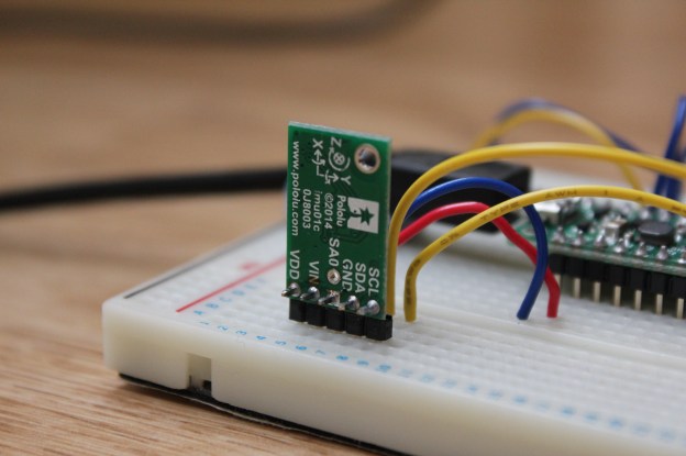
Pololu A-Star 32U4 Mini SV
Pololu MinIMU-9 v3
The MCU reads the MinIMU-9 v3 IMU data and publishes it as ROS messages on the following topics:
LSM303 accelerometer x, y, z values (“accel”)
LSM303 magnetometer x, y, z values (“magnet”)
L3G gyroscope x, y, z values (“gyro”)
LSM303 magnetometer heading value (“heading”), derived from the LSM303’s library, as the angular difference in the horizontal plane between the x axis and magnetic North
ROS has a very handy plotting tool for topics, called rqt_plot. Below is an example dump of all the IMU data.
IMU messages plotted in rqt_plot
Quaternion-based filter
Having spent too much time on the RPY approach already, I wanted to find a simple way to achieve a relatively stable orientation from the IMU readings. I ended up implementing the method from this AHRS maths tutorial from the Firetail UAV system. The method is explained very well in that link, so there is no need to go into the details. The only change I have made is in the calculation of the filter coefficient, based on a set time constant as was done previously. My version using a ROS subscriber on the PC side is again listed at the end of this post (imu_tf_broadcaster.cpp and .h files).
Videos
Here are two videos comparing the original RPY approach against the improved quaternion approach. The resulting IMU transform is published by tf, which is used by the robot model you see in RViz, the ROS visualisation tool. The model is generated using a URDF file; I will explain this in detail in a following post.
Although in both cases the rotation is fairly smooth, you can see the problems that the RPY filtering encounters when it nears the gimbal lock position (when the robot lies horizontally). For my purposes of orientating the robot, I think the current quaternion approach is perfectly suited. I doubt I will be needing to play around with Kalman filters and the likes, as I currently don’t need the precision that UAVs etc. may need!
So that’s it for IMUs and orientation for the time being. In my next post I will start detailing the current progress with the virtual bioloid in ROS, which was seen in the above videos.
Code (click to expand):
// Hardware:
// Pololu A-Star 32U4 Mini SV
// Pololu MinIMU-9 v3 (L3GD20H and LSM303D)
// Interlink FSR 400 Short (x6)

// Important! Define this before #include <ros.h>
#define USE_USBCON

#include <Wire.h>
#include <ros.h>
#include <std_msgs/Int16MultiArray.h>
#include <geometry_msgs/Vector3.h>
#include <std_msgs/Float32.h>
#include <AStar32U4Prime.h>
#include <LSM303.h>
#include <L3G.h>

// Set up the ros node and publishers
ros::NodeHandle nh;
std_msgs::Int16MultiArray msg_fsrs;
std_msgs::MultiArrayDimension fsrsDim;
ros::Publisher pub_fsrs("fsrs", &msg_fsrs);
geometry_msgs::Vector3 msg_accel;
ros::Publisher pub_accel("accel", &msg_accel);
geometry_msgs::Vector3 msg_magnet;
ros::Publisher pub_magnet("magnet", &msg_magnet);
std_msgs::Float32 msg_heading;
ros::Publisher pub_heading("heading", &msg_heading);
geometry_msgs::Vector3 msg_gyro;
ros::Publisher pub_gyro("gyro", &msg_gyro);
unsigned long pubTimer = 0;

const int numOfFSRs = 6;
const int FSRPins[] = {A0, A1, A2, A3, A4, A5};
int FSRValue = 0;
LSM303 compass;
L3G gyro;
const int yellowLEDPin = IO_C7;  // 13
int LEDBright = 0;
int LEDDim = 5;
unsigned long LEDTimer = 0;

void setup()
{
    // Array for FSRs
    msg_fsrs.layout.dim = &fsrsDim;
    msg_fsrs.layout.dim[0].label = "fsrs";
    msg_fsrs.layout.dim[0].size = numOfFSRs;
    msg_fsrs.layout.dim[0].stride = 1*numOfFSRs;
    msg_fsrs.layout.dim_length = 1;
    msg_fsrs.layout.data_offset = 0;
    msg_fsrs.data_length = numOfFSRs;
    msg_fsrs.data = (int16_t *)malloc(sizeof(int16_t)*numOfFSRs);

    nh.initNode();
    nh.advertise(pub_fsrs);
    nh.advertise(pub_accel);
    nh.advertise(pub_magnet);
    nh.advertise(pub_heading);
    nh.advertise(pub_gyro);

    // Wait until connected
    while (!nh.connected())
        nh.spinOnce();
    nh.loginfo("ROS startup complete");

    Wire.begin();

    // Enable pullup resistors
    for (int i=0; i<numOfFSRs; ++i)
        pinMode(FSRPins[i], INPUT_PULLUP);

    if (!compass.init())
    {
        nh.logerror("Failed to autodetect compass type!");
    }
    compass.enableDefault();

    // Compass calibration values
    compass.m_min = (LSM303::vector<int16_t>){-3441, -3292, -2594};
    compass.m_max = (LSM303::vector<int16_t>){+2371, +2361, +2328};

    if (!gyro.init())
    {
        nh.logerror("Failed to autodetect gyro type!");
    }
    gyro.enableDefault();

    pubTimer = millis();
}

void loop()
{
    if (millis() > pubTimer)
    {
        for (int i=0; i<numOfFSRs; ++i)
        {
            FSRValue = analogRead(FSRPins[i]);
            msg_fsrs.data[i] = FSRValue;
            delay(2);  // Delay to allow ADC VRef to settle
        }

        compass.read();
        gyro.read();

        // Compass - accelerometer:
        // 16-bit, default range +-2 g, sensitivity 0.061 mg/digit
        // 1 g = 9.80665 m/s/s
        // e.g. value for z axis in m/s/s will be: compass.a.z * 0.061 / 1000.0 * 9.80665
        //      value for z axis in g will be: compass.a.z * 0.061 / 1000.0
        // Gravity is measured as an upward acceleration:
        // Stationary accel. shows +1 g value on axis facing directly "upwards"
        // Convert values to g
        msg_accel.x = (float)(compass.a.x)*0.061/1000.0;
        msg_accel.y = (float)(compass.a.y)*0.061/1000.0;
        msg_accel.z = (float)(compass.a.z)*0.061/1000.0;

        // Compass - magnetometer:
        // 16-bit, default range +-2 gauss, sensitivity 0.080 mgauss/digit
        msg_magnet.x = (float)(compass.m.x);
        msg_magnet.y = (float)(compass.m.y);
        msg_magnet.z = (float)(compass.m.z);
        // Heading from the LSM303D library is the angular difference in
        // the horizontal plane between the x axis and North, in degrees.
        // Convert value to rads, and change range to +-pi
        msg_heading.data = ( (float)(compass.heading())*M_PI/180.0 );

        // Gyro:
        // 16-bit, default range +-245 dps (deg/sec), sensitivity 8.75 mdps/digit
        // Convert values to rads/sec
        msg_gyro.x = (float)(gyro.g.x)*0.00875*M_PI/180.0;
        msg_gyro.y = (float)(gyro.g.y)*0.00875*M_PI/180.0;
        msg_gyro.z = (float)(gyro.g.z)*0.00875*M_PI/180.0;

        pub_fsrs.publish(&msg_fsrs);
        pub_accel.publish(&msg_accel);
        pub_magnet.publish(&msg_magnet);
        pub_heading.publish(&msg_heading);
        pub_gyro.publish(&msg_gyro);

        pubTimer = millis() + 10;  // wait at least 10 msecs between publishing
    }

    // Pulse the LED
    if (millis() > LEDTimer)
    {
        LEDBright += LEDDim;
        analogWrite(yellowLEDPin, LEDBright);
        if (LEDBright == 0 || LEDBright == 255)
            LEDDim = -LEDDim;

        // 50 msec increments, 2 sec wait after each full cycle
        if (LEDBright != 0)
            LEDTimer = millis() + 50;
        else
            LEDTimer = millis() + 2000;
    }

    nh.spinOnce();
}
#include "imu_tf_broadcaster.h"

int main(int argc, char **argv)
{
    ros::init(argc, argv, "imu_tf_broadcaster");
    ros::NodeHandle n;
    ros::Rate loop_rate(1000);  // Hz

    Broadcaster broadcaster;

    ros::Subscriber accelSub   = n.subscribe("accel",   1000, &Broadcaster::accelCallback,   &broadcaster);
    ros::Subscriber magnetSub  = n.subscribe("magnet",  1000, &Broadcaster::magnetCallback,  &broadcaster);
    ros::Subscriber headingSub = n.subscribe("heading", 1000, &Broadcaster::headingCallback, &broadcaster);
    ros::Subscriber gyroSub    = n.subscribe("gyro",    1000, &Broadcaster::gyroCallback,    &broadcaster);

    while(n.ok())
    {
        //broadcaster.updateTimers();
        //broadcaster.updateRotation();
        broadcaster.tfBroadcaster->sendTransform(
            tf::StampedTransform(
                tf::Transform(broadcaster.getQ(), tf::Vector3(0.0, 0.0, 0.0)),
                ros::Time::now(),"odom", "imu_link"));
        loop_rate.sleep();
        ros::spinOnce();

//        std::cout << "dt: " << broadcaster.getDt() << std::endl;
//        std::cout << "q.x: " << broadcaster.getQ().x() << std::endl;
//        std::cout << "q.y: " << broadcaster.getQ().y() << std::endl;
//        std::cout << "q.z: " << broadcaster.getQ().z() << std::endl;
//        std::cout << "q.w: " << broadcaster.getQ().w() << std::endl;
//        std::cout << "----" << std::endl;
    }

    return 0;
}

Broadcaster::Broadcaster() :
    prevt(ros::Time::now().toSec()),
    dt(0.0),
    timeConst(1.0),
    filterCoeff(0.0)
{
    q.setRPY(0.0, 0.0, 0.0);
    tfBroadcaster = new tf::TransformBroadcaster();
}

Broadcaster::~Broadcaster()
{

}

void Broadcaster::accelCallback(const geometry_msgs::Vector3::ConstPtr& msg)
{
    accel.setX(msg->x);
    accel.setY(msg->y);
    accel.setZ(msg->z);
}

void Broadcaster::magnetCallback(const geometry_msgs::Vector3::ConstPtr& msg)
{
    magnet.setX(msg->x);
    magnet.setY(msg->y);
    magnet.setZ(msg->z);
}

void Broadcaster::headingCallback(const std_msgs::Float32::ConstPtr& msg)
{
    heading = msg->data;
}

void Broadcaster::gyroCallback(const geometry_msgs::Vector3::ConstPtr& msg)
{
    dt = ros::Time::now().toSec() - prevt;

    gyro.setX(msg->x);
    gyro.setY(msg->y);
    gyro.setZ(msg->z);

    angularVel.setX(gyro.x());
    angularVel.setY(gyro.y());
    angularVel.setZ(gyro.z());

    filterCoeff = timeConst / (timeConst + dt);

    // Use accelerometer and magnetometer data to correct gyro drift
    correctOrientation();

    updateRotation();

    prevt = ros::Time::now().toSec();

//    std::cout << "angularVel x: " << angularVel.x() << std::endl;
//    std::cout << "angularVel y: " << angularVel.y() << std::endl;
//    std::cout << "angularVel z: " << angularVel.z() << std::endl;
//    std::cout << "----" << std::endl;
}

void Broadcaster::updateRotation()
{
    // New quaternion, from axis-angle notation for gyro
    tf::Quaternion qNew(angularVel.normalized(), angularVel.length()*dt);

    // Update previous value
    q *= qNew;
    q.normalize();
}

void Broadcaster::correctOrientation()
{
    // Use acceleration data only if vector is close to 1 g
    if ( fabs(accel.length() - 1) <= 0.1 )
    {
        // These vectors have to be perpendicular.
        // As there is no guarantee that North is perpendicular to Down,
        // set North to the cross product of East and Down.
        // Gravity is measured as an upward acceleration.
        tf::Vector3 Down(accel);  // Should be -accel, but not sure why this produces inverted axes!?
        tf::Vector3 E = Down.cross(magnet);
        tf::Vector3 N = E.cross(Down);

        Down.normalize();
        E.normalize();
        N.normalize();

        // The rows of the rotation matrix represent the coordinates in the original
        // space of unit vectors along the coordinate axes of the rotated space
        tf::Matrix3x3 gyroRotMat = tf::Matrix3x3(q);

        // Correction vector
        tf::Vector3 cv = ( N.cross(gyroRotMat.getRow(0)) +
                           E.cross(gyroRotMat.getRow(1)) +
                           Down.cross(gyroRotMat.getRow(2)) ) * filterCoeff;

        angularVel += cv;
    }
}