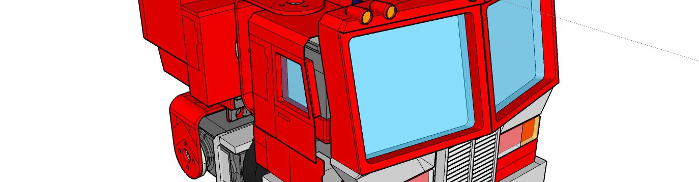
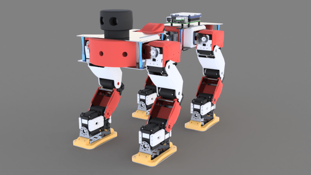
After importing into Fusion 360 and adding a touch of texturing, I added it to the robot model to show a sense of scale. It needs a 3D printed mount to be properly attached to the top of the front body; or better yet, a re-design of the front bumper to integrate the camera inside it, giving an unobstructed forward-facing view.
The camera will be controlled by PC/laptop for now, but will later need to be controlled by a beefier on-board controller.
Sensor mount
The mount will be made with some standard Bioloid parts and 2 additional AX-12 servo motors. Here is the current concept:
Over the last few weeks I have been thinking about the overall controller architecture, 3D printing some test Raspberry Pi cases, and updating the Python test software.
Plotter updates
Timed operations
After refactoring the giant single-file script from the previous post, I noticed the script was actually running very inefficiently, partly down to the fact that the 2D canvas had to redraw the whole robot on every frame, but also because of the way some of the threaded classes (e.g. input handler, serial handler) were inadvertently constantly interrupting the main thread, because they were relying on use of the root window’s after() method. The timing loops are cleaned up now and the code runs much more efficiently.
Here is an example I figured out, of how to create a class to run a function in a separate thread, with a defined time interval, that is pausable/stoppable. It subclasses the Thread class, and uses the help of an Event object to handle the timing functionality. After creating an object of this class, you call its start() method, which invokes the run() method in a separate thread. The pause(), resume() and stop() methods perform the respective actions. The example is a stripped-down version of an input handler, which applies the equations of motion to user inputs, as shown in a past post.
import threading
from time import time
import math
class InputHandlerExample(threading.Thread):
    def __init__(self):
        # Threading/timing vars
        threading.Thread.__init__(self)
        self.event = threading.Event()
        self.dt = 0.05  # 50 ms
        self.paused = False
        self.prevT = time()
        self.currT = time()
        self.target = 0.0
        self.speed = 0.0

        # Input vars
        self.inputNormalised = 0.0

    def run(self):
        while not self.event.isSet():
            if not self.paused:
                self.pollInputs()
            self.event.wait(self.dt)

    def pause(self):
        self.paused = True

    def resume(self):
        self.paused = False

    def stop(self):
        self.event.set()

    def pollInputs(self):
        # Upate current time
        self.currT = time()

        # Get user input somehow here, normalise value
        #self.inputNormalised = getInput()

        # Update target and speed
        self.target, self.speed = self.updateMotion(
            self.inputNormalised, self.target, self.speed)

        # Make use of the returned target and speed values
        #useResults(target, speed)

        # Update previous time
        self.prevT = self.currT

    def updateMotion(self, i, target, speed):
        m = 1.0
        u0 = speed

        # Force minus linear drag
        inputForceMax = 1000
        dragForceCoef = 5
        F = inputForceMax*i - dragForceCoef*u0
        a = F/m
        t = self.currT - self.prevT

        # Zero t if it's too large
        if t > 0.5:
            t = 0.0
        x0 = target

        # Equations of motion
        u = u0 + a*t
        x = x0 + u0*t + 0.5*a*math.pow(t, 2)

        return x, u
3d plot
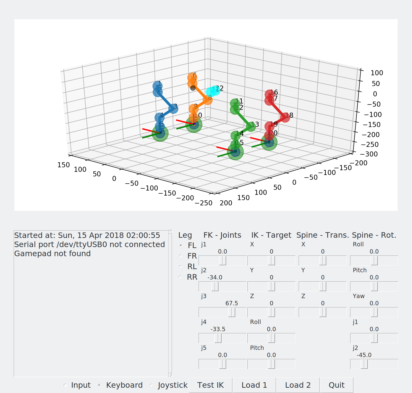
So far the 2D representation of the robot worked OK, but it has its limitations. So I finally decided to put some effort into updating the representation of the robot. I went with matplotlib and its 3D extensions with the mplot3d toolkit.
The joints are simply represented using the scatter() function, while the lines are simply drawn with plot(). The text() function overlays the number of the joints over the joint positions. The leg target widgets use a combination of the above functions. The 3D plot is updated using the FuncAnimation class.
Since this designed for Matlab-style plotting rather than a simulator, the performance is still somewhat lacking (not as fast as the 2D canvas), but I wanted to be able to get something working fairly quickly and not waste too much time with something like OpenGL, since my aim is to have a test program and not build a 3D simulator from scratch. There’s always ROS and Gazebo if I need to take this further!
As a side note, I have added the option in the main program to be able to select between 2D or 3D drawing mode, as well as no drawing, which should be useful for speeding up execution when running on the Raspberry Pi in headless mode (no screen).
Here is a screenshot and a video of the results:
Canvas redrawing
Another efficiency issue was the fact that previously the canvas was cleared an then redrawn from scratch on every frame update. To improve efficiency, both for the 2D and the 3D cases, the drawing classes now have structs to keep track of all element handles, and the redraw functions move the elements to their updated positions. For the 2D case (TkInter canvas), this is done with the coords() method. For the 3D case (matplotlib) it was a bit trickier, but I managed it with a combination of methods:
For lines (plot): set_data() and set_3d_properties()
For points (scatter): ._offsets3d = juggle_axes()
For text overlay (text): set_position and set_3d_properties()
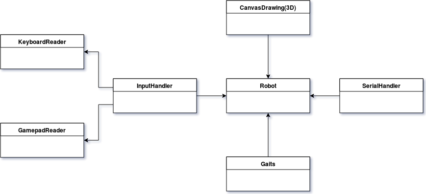
Updated class diagram
The interaction between the different elements is cleaned up and now looks like this:
Hardware architecture
Now, to make a switch and talk a bit more about the hardware, here is the current plan of how all the components will probably look like:
I have in fact got two Raspberry Pis now, a Pi 3 Model B as well as a Pi Zero W. Both now have built-in WiFi, but I am going with the larger Pi 3 as the current choice for main controller, favouring the quad-core CPU over the Zero’s single core.
I tried 3D printing some cases from Thingiverse for each Pi, and here are the results. A great plus point of the Pi 3 case is that it has mounting points which will be easy to locate on the main robot body.
You can find my builds and their sources on Thingiverse:
After 3D printing a few more plastic parts and cutting all the aluminium plates, the custom chassis is finally complete! Below are some quick notes on the progress over the last weeks.
More 3D printed parts and painting
I printed off some of the remaining parts of the chassis. The battery compartment was best printed upright with minimal support structure needed. The rear bumper was trickier than the front bumper, because of the additional hole space for the battery, so I found it was best to print upright, with a raft and curved supports at the bottom.
Once all parts were printed, and some more sanding, I spray-painted all the parts with plastic primer, then blue paint, and finally clear sealer.
Metal parts
I was initially thinking of finding an online service to cut out the aluminium chassis parts, but then decided it would be faster and cheaper to just get some sheets 1.5 mm thick aluminium sheets from eBay and cut them on a jigsaw table.
I used Fusion 360’s drawing tool to export to PDF the parts I needed to cut out: four chassis plates and four foot plates. I then printed them in actual scale and glued them on the aluminium to uses as traces.
Assembly
I threaded the holes on all the 3D parts, which were either 3 mm wide where the aluminium plates attach, or 2 mm at the leg and spine bracket attachment points.
Using a tap for the 3 mm holes worked pretty well, but the 2 mm holes were more prone to being stripped or too loose, so manually threading the holes with the bolts worked better. Another issue was the infill surrounding the internal thread cylinder sometimes being a bit too thin. In retrospect, I’d try designing the 3D parts to use heat-set or expandable inserts, especially for the smaller threads.
The servo brackets attaching to the chassis have a large number of holes (16 for each leg and one of the spine brackets, and 12 for the other spine bracket) so the screws so far seem to secure the brackets well enough. The spine section is under a lot of stress from the wight of the whole chassis and legs, so it will not be able to withstand much twisting force, and the servos may not be strong enough at this area, but I will have to test this in practice with new walking gaits.
Conclusions
The custom chassis has finally made it from a 3D design to a reality, with relative success so far. Some of the threaded holes on the 3D parts are not as strong as I’d like, the AX-12 may be under-powered for the spine connection, and the brackets anchoring the spine may be the first to give way due to twisting forces. Also the chassis as a whole would benefit form weight-saving exercise and perhaps being thinned down. But this has only been the first iteration of the main chassis, and the robot design has now become a reality and seems to stand up well. The next step will see how it performs some of the basic walking gaits!
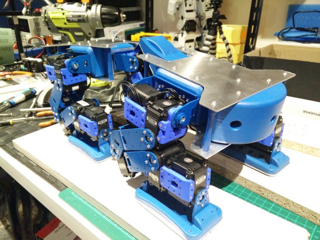
With enough motors and brackets to build a second leg, the hardware build continues! I have spray-painted all the metal brackets to go with an all-blue colour scheme. The Robotis plastic brackets were hard to source online, so I got them printed by Shapeways.
I re-purposed the test rig frame used for the single leg to make a platform for the two legs. It’s made out of MakerBeam XL aluminium profiles which are very easy to change around and customise to any shape. This base will work well until I get the rest of the plastic parts 3D printed and the metal parts cut.
I also had enough parts and motors to assemble the 2-axis “spine”, but the main frame is not yet built so it that part is on the side for now.
Here are a few photos of the build:
In the next post I will concentrate on software updates to the leg and spine kinematics.
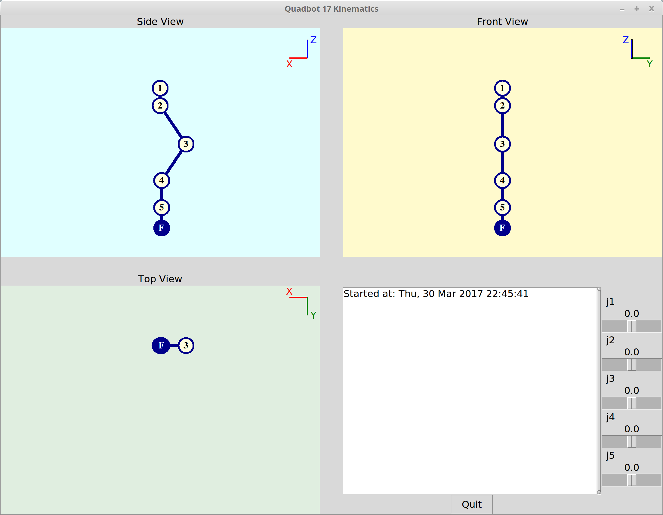
I also made a simple Python applet to verify the maths and visualise the leg’s poses. I used Tkinter and three Canvas widgets to show orthogonal views.
The reason I am testing the maths in a quick Python program is that I want to be able to port them easily over to Arduino, as my latest aim is to drop the Raspberry Pi and A-Star 32U4 LV Pi expansion module (shown in some of the latest CAD models) in favour of trying out an ArbotiX controller. A benefit with the latter is that I wouldn’t need a Dynamixel-to-USB converter (e.g. USB2AX) or separate motor power supply.
Next up will be to work out the Inverse Kinematics.
Link
Twist
Link
Length
Link
Offset
Joint
Angle
j
alpha_i-1
a_i-1
d_i
theta_i
1
0
0
0
th_1
2
pi/2
29.05
0
th_2 – 34
3
0
76.919
0
th_3 + 67.5
4
0
72.96
0
th_4
5
-pi/2
45.032
0
th_5
D-H Parameters
Quadbot kinematics applet, zeroed position
Quadbot kinematics applet, test position using sliders
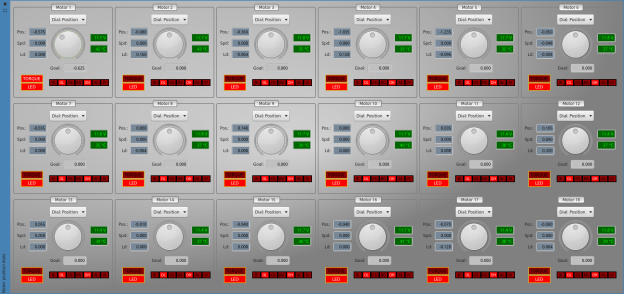
I have made some updates to the motor dials which control the motor positions. They can now change mode and control motor speed and load. Also, the GUI is regularly updated with some important feedback from each motor: motor voltage and temperature, LED and torque on/off state, and feedback on all the alarm states.
The updated Motor Dials, controlling 18 AX-12 motors.
Close-up of single dial and feedback indicators.
At this point I’m starting to think that an internal model of all the motor control table data would be useful at this point! Rather than classes making direct requests to the motor controller to receive motor information, all the state data could be kept by the controller and updated regularly. Classes would then simply get the latest data from this model when needed. This is however partially the way the controller works already, as it has a model of the ROS-style joint states which hold present positions, present speeds and present torques (loads), as well as goal positions, moving speeds and torque limits. The joint states are published continuously by a ROS publisher. Present and goal positions are the most important data, as the AX-12 by default only performs position control. Moving speed is simply the speed that the motor will use to move between positions, so cannot be used for e.g. a velocity feedback loop. “Torque” is a bit of a misleading term here, as there is no torque sensing in the motors. Torque sensors are only available in much more expensive motors than these. The load values reported by the AX-12 are related to the motor current, but cannot be read while the motor is actually moving. Two notable sources which have more detailed information on this somewhat unclear measurement can be found here on the RoboSavvy forum and here.
I think I’m done with updating these graphical widgets for the time being, as it is detracting from the main goals of exploring MoveIt! and getting the robot walking.