

In this post I will cover the current state of my ROS setup for controlling the Bioloid’s motors and custom hardware.
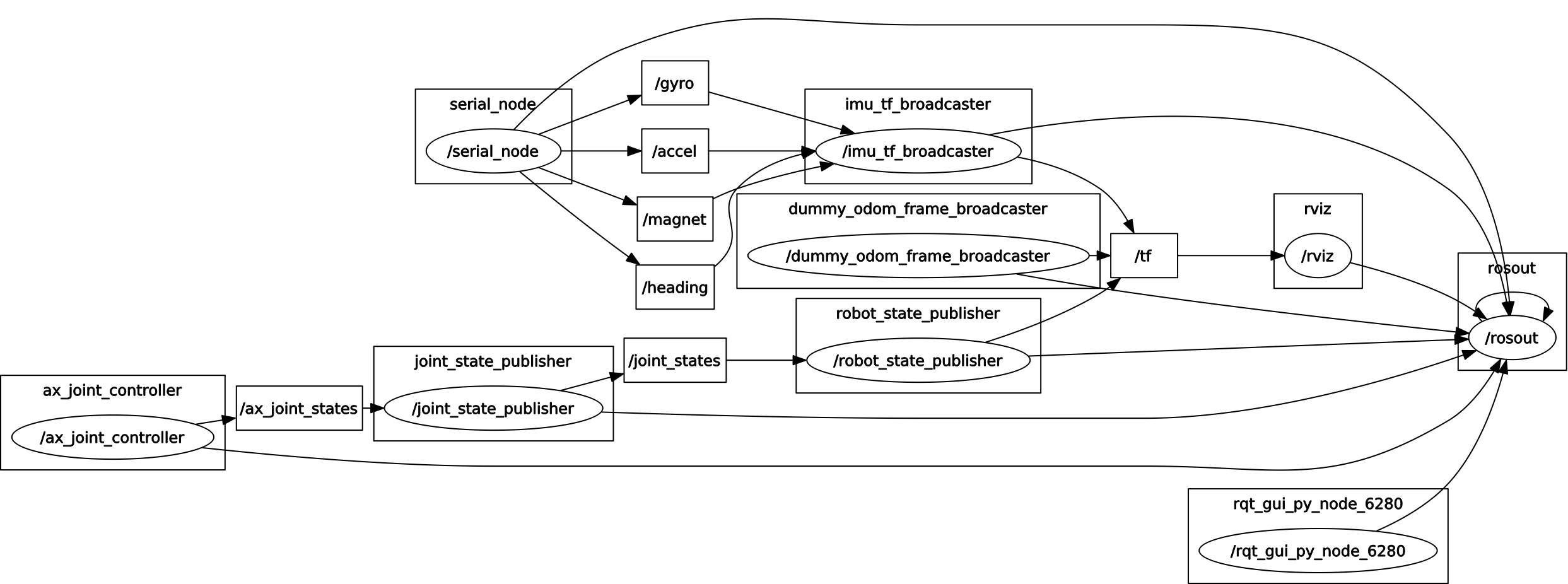
The rqt_graph package provides a way of visualising the interconnections between all running ROS nodes. The following graphs show the current setup:
-

- ROS graph of current setup.
-
- ROS graph, with debug info shown.
Here is a breakdown of the running nodes:
- bioloid_sensors (MCU Arduino code): The MCU is running an Arduino program using the rosserial_arduino library, and publishes the IMU’s data as ROS messages over serial-to-USB. The rosserial package was useful as an easy way of sending ROS messages from the MCU to the controlling PC.
- serial_node: This is a node included in the rosserial_python package, which reads serial data from the MCU.
- imu_tf_broadcaster: This is a custom node which uses the IMU’s data to calculate the robot’s orientation, as detailed in this previous post.
- dummy_odom_frame_broadcaster: This is a static_transform_publisher node from tf, which transforms from the map to the odom frame without any actual change in orientation or position. This is simply to keep in line with the ROS conventions, as explained in this previous post.
- ax_joint_controller: This is another custom node for communicating with the AX-12 servos. This is a work-in-progress, but currently acts as a ROS wrapper around the USB2Dynamixel/USB2AX library. It publishes the servo positions (in radians) as a ROS sensor_msgs JointState message, on the ax_joint_states topic. It also runs a number of ROS services for controlling the servos from other ROS nodes. These are either higher level commands (such as for setting all motors to home position), or low level commands for directly reading from or writing to the AX-12 Control Table’s addresses.
- joint_state_publisher: The joint_state_publisher is a tool for setting and publishing joint state values for a given URDF file. The node here reads the values from the ax_joint_states topic (by setting the source_list parameter) and publishes on the joint_states topic. I suppose this node could currently be bypassed entirely, however it does provide a nice GUI window for visualising the joint positions as sliders, and is also useful for moving the robot’s joints in RViz when ax_joint_controller is offline.
- robot_state_publisher: The robot_state_publisher works in tandem with the joint_state_publisher and publishes the state of the robot to tf. The robot_state_publisher reads the configuration of the kinematic chain from the URDF file (set by the robot_description parameter). The set up of the URDF file has been covered in a previous post. The virtual model of the robot is then displayed in RViz, with joint positions reflecting those of the physical robot.
That is about it for the current setup. I have some work-in-progress nodes which interface with the above framework and test some of the robot’s motions, so in a following post I will discuss these and show some new videos of the physical robot in action!


