My humanoid robot updates have temporarily taken a backseat due to some other distractions, such as the FPV quadcopter, and now this! Updates on the Bioloid will still continue however, as I am far from done with it.
So as another side-project, I’ve been thinking about trying to build a custom robot from the ground-up, rather than basing it on an existing platform like the Bioloid.
CAD software
I have been using FreeCAD for the Bioloid project, which is a great free tool but somewhat hard to use and lacking many of the features found in modern CAD software.
As I need to design a large number of new parts, I’ve been looking around for a good CAD software with most or all of the following key features:
- free, or at least licenced for hobbyist use
- parametric modelling
- export to STL
- 3D printing support tools a plus, but not necessary
- nice renderer?
Autodesk’s line of tools seem to meet these requirements very well. Autodesk 123D seemed like an excellent choice, with more advanced features than its sibling Tinkercad, a CAD program which runs inside a web browser. However, Autodesk has recently been restructuring its suite of tool according to this announcement, so this lead me to check out Fusion 360.
It has a very flexible licensing model, which means it can be used for free as a student, educator, start-up and most importantly, as an enthusiast (non-profit). I have only been using it for a few days, but so far it seems impressive. It works very similar to SolidWorks, and has a number of useful features such as direct integration with various 3D printing tools and services, and an easy-to-use renderer. One thing that may be seen as a downside is the fact that everything is stored on the cloud, but local backups are possible.
Components & 3D printing
The main design of the robot will be centred around the use of Dynamixel’s AX range of servos, as they are the most competitively priced motors I’ve found for the power and features they offer. Most other high-torque servos are prohibitively expensive, considering I will need about 16 and each costs over £100!
The exact model will probably be the AX-12A, which is an improved version of the AX-12+ used on the Bioloid. I might be able to stretch to the faster, more expensive AX-18A, however as their external design is identical, any frames used will be compatible with both.
For the basic servo joints I will be using a combination of the plastic frames in the Robotis range, as well as possibly some metal frames by Trossen Robotics. The rest of the robot will be designed with 3D printed parts in mind. Whether I go for an expensive online 3D printing service or try and revive my 3D printer remains to be seen.
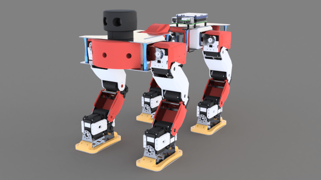
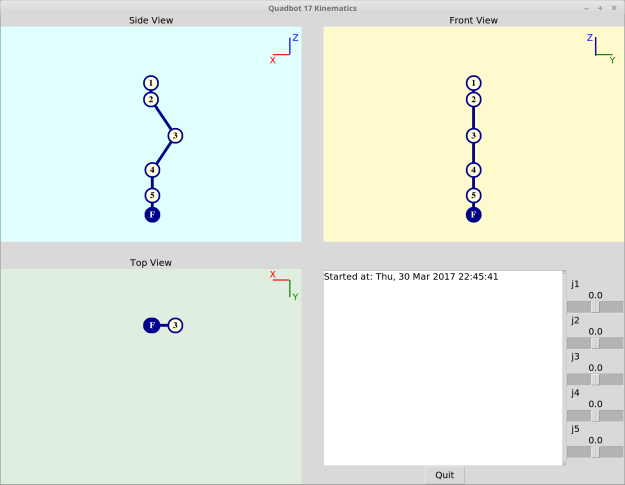
Inspiration:
These are a few images as well as designs by other hobbyists which I am using as inspiration:


