Overview
The following program was an exercise in basic robot manipulator theory, as well as turning that theory into practice. This was one of my first programming attempts using OpenGL and SDL, and the robot code was written from scratch.
For the OpenGL/SDL part, I got started with some great tutorials from NeHe Productions.
The robot
The robot manipulator is set up as an R-R-R configuration (3 revolute joints) and moves on a 2D plane for the time being, even though the interface is in 3D. The manipulator setup and equations for describing the forward and inverse kinematics (IK) were inspired by this tutorial. The rotation and transformation matrices were set up with the help of the Eigen library for matrix manipulation. The forward kinematics solution is essentially straightforward, given that the user can control target tool position and orientation. A numerical method was used as a solution to the IK.
Forward kinematics
The parameters 


In order to end up with the representation of tool frame w.r.t. world frame, the rotation and translation matrices are multiplied in series, starting from the origin and moving towards the tool frame. The tricky part was to visualise the results in 3D using OpenGL commands. The robot links and joints were represented by a chain of appropriately oriented cylinders. I presented the rotation/transformation matrices as having three dimensions, as I hope to expand on this program and create an arm which can operate in 3D.
Inverse kinematics
The rotation matrix for rotation of tool frame w.r.t. world frame is:

The angle of the tool w.r.t. to the world frame can also be written as:

Solving the IK problem comes down to a system of three non-linear equations:


These equations can be solved by applying a gradient descent algorithm.
For a system of non-linear equations, we have:
![G(x) = \begin{matrix} [ y_1(\mathbf{x}) & y_2(\mathbf{x}) & y_3(\mathbf{x}) ]^T \end{matrix}](https://s0.wp.com/latex.php?latex=G%28x%29+%3D+%5Cbegin%7Bmatrix%7D+%5B+y_1%28%5Cmathbf%7Bx%7D%29+%26+y_2%28%5Cmathbf%7Bx%7D%29+%26+y_3%28%5Cmathbf%7Bx%7D%29+%5D%5ET+%5Cend%7Bmatrix%7D+&bg=ffffff&fg=444444&s=0&c=20201002)
![\mathbf{x} = \begin{matrix} [ x_1 & x_2 & x_3 ]^T \end{matrix}](https://s0.wp.com/latex.php?latex=%5Cmathbf%7Bx%7D+%3D+%5Cbegin%7Bmatrix%7D+%5B+x_1+%26+x_2+%26+x_3+%5D%5ET+%5Cend%7Bmatrix%7D+&bg=ffffff&fg=444444&s=0&c=20201002)
The objective function (to minimise):

For each next guess 

, where 
The aim is to find a suitable 

In the robot manipulator’s case, 
where:
![\mathbf{\theta} = \begin{matrix} [ \theta_1 & \theta_2 & \theta_3 ]^T \end{matrix}](https://s0.wp.com/latex.php?latex=%5Cmathbf%7B%5Ctheta%7D+%3D+%5Cbegin%7Bmatrix%7D+%5B+%5Ctheta_1+%26+%5Ctheta_2+%26+%5Ctheta_3+%5D%5ET+%5Cend%7Bmatrix%7D+&bg=ffffff&fg=444444&s=0&c=20201002)


and 

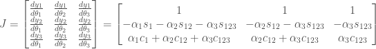
Jacobian:
Images – Video

RRR robot GUI. The green square indicates the required target position that the manipulator end effector must achieve.

RRR robot GUI. The red square indicates that the target position is outside the arm’s reachable workspace.
Downloads
The program was compiled on Linux, Ubuntu 10.04 (kernel v2.6.32-26-generic). To compile, you will need to have these third-party libraries installed: OpenGL, SDL, Eigen v.2
Source: robotRRR.cpp
Makefile: Makefile
(Remove the .doc extensions, I had to add them to get the files uploaded on WordPress!)
Controls:
W,A,S,D – Move end-effector target on 2D plane
Q,E – Rotate end-effector target orientation left/right
Arrow keys – Rotate camera
Future goals
I hope to expand on this basic robot arm framework in many ways. Some initial tasks are:
- Organise the code (multiple files, header files, perhaps set up an Eclipse project).
- Expand the GUI’s functionality.
- Add a revolute joint that will allow the arm to operate in 3D. This will be a more challenging coding project but will result in a much more useful arm!
