After importing into Fusion 360 and adding a touch of texturing, I added it to the robot model to show a sense of scale. It needs a 3D printed mount to be properly attached to the top of the front body; or better yet, a re-design of the front bumper to integrate the camera inside it, giving an unobstructed forward-facing view.
The camera will be controlled by PC/laptop for now, but will later need to be controlled by a beefier on-board controller.
Sensor mount
The mount will be made with some standard Bioloid parts and 2 additional AX-12 servo motors. Here is the current concept:
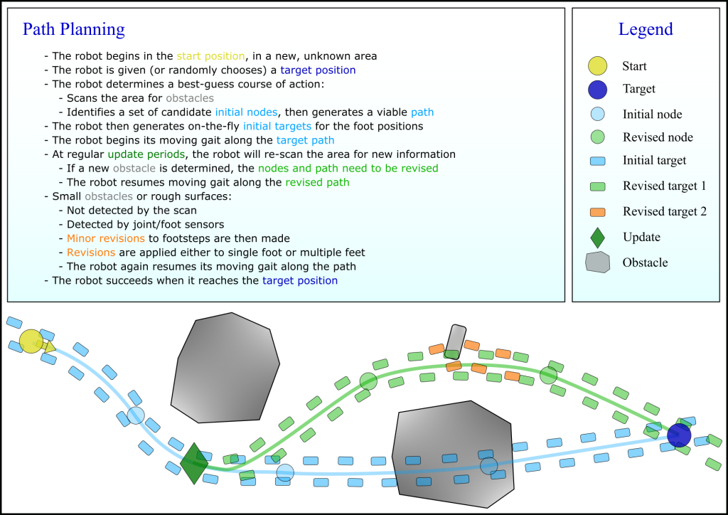
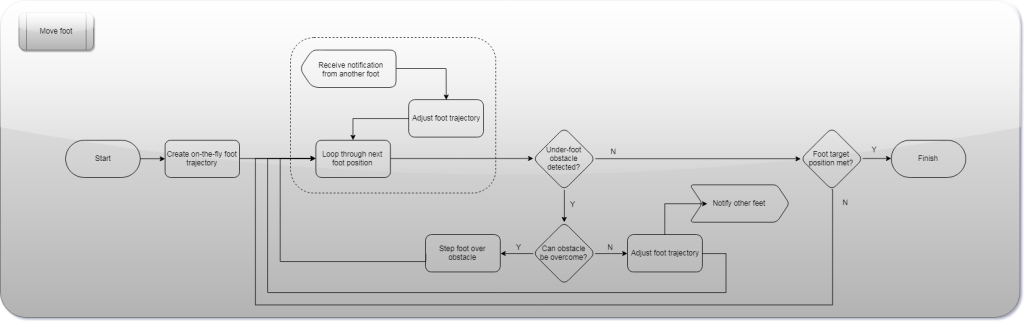
The current walking gait system is mostly just a test of the kinematics and user inputs. To make the robot truly manoeuvrable, it requires sensors and better foot positioning techniques. The following diagrams are my initial attempt at trying to decide how exactly to achieve this. This is a very first look, and the actual implementation will probably vary significantly, but it provides a good starting point to start exploring further ideas:
The problem is broken down into three levels:
Level 1: Navigation
Scanning of area with 3D sensor
Making decisions on how to approach a goal
Level 2: Stepping
Deciding on appropriate gait parameters
Generating the foot target positions within the environment
Level 3:
Planning and executing the foot trajectories
Reacting to any obstacles encountered by the feet
Required hardware updates
These are the current hardware updates that will be needed soon, in order to improve and then progress further than basic walking gaits:
1) Torsion springs
Reducing the load on critical joints will be achieved by adding torsion springs to the hip/knee motors.
2) Foot sensors
This is a must in order for the robot feet to account for rough or uneven terrain, and load distribution of the robot. I’ve been looking at ways of adding foot sensors via the AX-12 daisy-chain and not separately, to avoid adding multiple cable bundles to each foot. The only off-the-shelf existing option I have found is too expensive (ROBOTIS OP2-FSR Set). However, a perfect open-source solution looks like the Force foot design by Rhoban (thanks to B[] for the suggestion!).
3) 3D sensor
The ability to get useful information from the environment can be achieved by adding a 3D sensor head to the robot, such as an Intel RealSense depth camera. This however will have significant knock-on effects on the rest of the design, such as on power consumption, and the need to have a powerful on-board processing, which the Raspberry Pi won’t be able to hack.
More future ideas
Better control
Replacement of the motors would only be an option in an entirely new hardware iteration of this robot, as the design is based around the AX-12s. However, I may explore upgrades to the motor control, beyond AX-12s’ internal controllers with compliance. Two potential options:
External PID loop wrapped around the existing internal controller
Firmware updates such as this one, in order to have direct PID control
Modelling
I would like to better understanding of the dynamics of leg locomotion, and developing a Simulink model would help. Something like this but on four legs would really be the ultimate goal!
I have recently been prioritising update logs on the Hackaday page of this project, due to the previous deadline! For completeness, here are some more details about the process in building the add-on tail.
The CAD model went through a couple of iterations before deciding on the final form: from 8 polygonal sections to six smoother and smaller sections.
When 3D printing, the base section went through a re-design, since the original idea of just gluing the small section to the base was clearly not going to provide enough stability. I also removed yet another link, to avoid having the tail ending up too big and heavy.
The base section of the tail now screws onto two of the existing holes on the rear base, meaning there is no need to modify it, other than replacing two M3 bolts with longer ones.
The tail links are all held together with a 150 mm long, 5 mm diameter spring, scavenged from a flexible long reach pick-up tool.
To make the models easy to 3D print, I sliced them all down the centre, then glued the halves together Loctite super glue works well with PLA (the gel type works best). There were a few failed prints in the process, which I put down to rushing, and using PLA which has been out in the air gathering moisture for several months! Prints were made on a Flashforge Creator Pro, with 15% infill.
Here are some pictures of the printing and assembly progress, leading to the final result: