Tag Archives: Qt

Balancing ideas

I had briefly tried in the past a simple balancing function using a PID controller, which aims to balance the Bioloid using the ankle motors, by trying to keep the IMU (accelerometer/gyro) vertical. The result was mixed success, but was only an early test. I am considering revisiting this balancing test, but this time using a number of PID controllers to control multiple groups of leg motors(e.g. hips, knees and ankles), while also using the GUI to make testing faster and easier.


On another note, I recently came across the Nengo Neural Simulator, which is a framework for creating neural networks of leaky integrate-and-fire (LIF) neurons for creating complex computational models. It has been used to create Spaun, the world’s largest functional brain model which is able to perform a number of functions such as vision, memory, counting, as well as drawing what is sees by controlling a simple arm.

What stands out is how easy it is to use the Nengo GUI to build neural networks. The interface runs in the browser and visualisations of neuron spiking activity and other metrics are easily shown for each graphical object. There is also support for scripting in Python. Installing it and trying it out for yourself is pretty simple, just follow the Getting Started guide here.


It would be really interesting to see if some form of PID controller could be built using Nengo, and then used to control the Bioloid’s balancing!

Qt Style Sheets and C++

This is a quick post to show some more updates to the styling of the GUI.

I have been experimenting with customising the look-and-feel of my GUI using Qt Style Sheets (QSS) which are closely related to HTML Cascading Style Sheets (CSS).

Customised widgets

I have so far customised most of the widgets which appear in the GUI, as shown in the following examples. I have chosen a blue/grey theme throughout, with some exceptions for specialised widgets and items.

Code

Initially the style sheets were embedded in QStrings inside the code, but they were dotted around various classes which meant a lot of code was duplicated as I kept adding content. I then moved the style sheets (QSS) for each widget to a separate text file, and set them via each class individually. Finally I found a way of greatly simplifying this by putting all the code into one single file. This is applied through the program’s main window (QMainWindow). Exception widgets use custom QSS Selector ID, which is set with setObjectName(). This is a nice way of applying specialised styles to specific widgets, such as e.g. a button that needs to stand out.

Here are two QSS examples of the standard and special button shown earlier:

QPushButton {
    background-color: qlineargradient(x1: 0, y1: 0, x2: 0, y2: 1, stop: 0 lightsteelblue, stop: 1 steelblue);
    border-color: #8F8F91;
    border-style: outset;
    border-width: 4px;
    border-radius: 10px;
}
QPushButton:flat {
    border: none; /* no border for a flat push button */
}
QPushButton:default {
    border-color: royalblue; /* make the default button prominent */
}
QPushButton:pressed {
    background-color: qlineargradient(x1: 0, y1: 0, x2: 0, y2: 1, stop: 0 royalblue, stop: 1 dodgerblue);
    border-style: inset;
}
QPushButton#redPushButton {
    color: white;
    background-color: red;
    border: solid lightgrey;
    border-style: outset;
    border-width: 4px;
    border-radius: 4px;
}
QPushButton#redPushButton:flat {
    border: none;  /* no border for a flat push button */
}
QPushButton#redPushButton:default {
    border-color: grey;  /* make the default button prominent */
}
QPushButton#redPushButton:pressed {
    color: red;
    background-color: darkred;
    border: solid red;
    border-style: inset;
    border-width: 4px;
    border-radius: 4px;
}

As usual, the latest source code is available on GitHub if you want to have a look.

Motor dials updated

I have made some updates to the motor dials which control the motor positions. They can now change mode and control motor speed and load. Also, the GUI is regularly updated with some important feedback from each motor: motor voltage and temperature, LED and torque on/off state, and feedback on all the alarm states.

At this point I’m starting to think that an internal model of all the motor control table data would be useful at this point! Rather than classes making direct requests to the motor controller to receive motor information, all the state data could be kept by the controller and updated regularly. Classes would then simply get the latest data from this model when needed. This is however partially the way the controller works already, as it has a model of the ROS-style joint states which hold present positions, present speeds and present torques (loads), as well as goal positions, moving speeds and torque limits. The joint states are published continuously by a ROS publisher. Present and goal positions are the most important data, as the AX-12 by default only performs position control. Moving speed is simply the speed that the motor will use to move between positions, so cannot be used for e.g. a velocity feedback loop. “Torque” is a bit of a misleading term here, as there is no torque sensing in the motors. Torque sensors are only available in much more expensive motors than these. The load values reported by the AX-12 are related to the motor current, but cannot be read while the motor is actually moving. Two notable sources which have more detailed information on this somewhat unclear measurement can be found here on the RoboSavvy forum and here.


I think I’m done with updating these graphical widgets for the time being, as it is detracting from the main goals of exploring MoveIt! and getting the robot walking.

Sensor grapher

A sensor plotting window has now been added to the GUI, which shows all data from the IMU and pressure sensors. The accelerometer, magnetometer, gyroscope, heading data and Force Sensing Resistors’ (FSRs) data are all published as ROS messages as shown in this post, so reading them in the Qt GUI is fairly straightforward, in a similar way to how the joint states are being read. The graphs are made using a third party library for Qt called QCustomPlot.

Each graphs show a scrolling 10 second window of buffered data, which can be paused/played. With QCustomPlot it’s easy to enable user interactions with graphs (drag axis ranges with mouse, zoom with mouse wheel, etc.), so I enabled this option whenever the graph is in a paused state.

The y-axis units are currently showing raw data, which I will probably update to show standard values.

Screenshot from 2016-04-03 19-46-07.png

A useful thing I found in Qt with QDockWidget, which is used to create dockable/floating sub-windows, is that these widgets can also be tabbed to save space on the screen. How can this be done in code you may ask? The useful functions I found were: setDockNestingEnabled() (or setDockOptions()), tabifyDockWidget() for QMainWindow, and raise() to select the default tabbed dock widget you want displayed.

That’s pretty much all there is to the sensor grapher. I might add more features to it in the future, but for now it does the basics!

List of ideas

As I have many ideas floating about on what to work on next, I made a list to see try and see which ones are worth prioritising:

  • GUI updates
    • Graph for visualising sensor data
    • Improved motion editing
  • Static balancing
  • Implement MoveIt! trajectory following via GUI
  • Walking routines
  • Advanced movement: Trajectories generate from MoveIt!, combined with active balancing as the robot moves

This is just an initial list, which I hope to expand on in the future.

My immediate plans right now are to continue tidying up some GUI graphical details, implement a simple sensor data plotter (I know rqt_plot does a fairly good job of this already, but I’d like to have sensor data integrated in my GUI) and get back to trajectory generation tests using MoveIt!

More software updates

With the new PC’s development tools up and running, I’ve made a number of updates to the GUI side of things, as well as the background joint controller node. Here are some of the most important from this month.


Joint controller updates

An issue I was having with the joint controller node – a main function of which is to act as a ROS wrapper class around the Dynamixel API – was that I seemed to be getting erroneous values when executing a simple one-off read from the motors. I suspected this was related to the fact that the node is also constantly reading the motors’ feedback values as fast as possible in its main loop. Even though the Dynamixel library seems to have checks for a busy comms bus, there was likely some issue with multiple threads trying to access the bus. This was easily fixed by using ros::spinOnce() in the main loop instead of using an AsyncSpinner which starts up a separate thread.

There is still some problem where positional values for some of the motors seem to be getting constantly corrupted, but only when all the torques are enabled and the motors are struggling to achieve all their goals positions (making the typical whining noise that servos have). I’ve yet to narrow down if this is a software issue or not.

Update to read/write services

The ROS read/write services have been simplified now, and two of the most useful commands are the ones that perform a sync read and write across a number of motors. As these are ROS services they can also be called from a terminal command line. For example, to receive the current position, current speed and current torque of motors 1, 3 and 5 all at once, you can run:

rosservice call /ReceiveSyncFromAX '[1, 3, 5]' 36 3

36 is the start address for the low byte of the present position, and 3 indicates the number of control table values, including the start address, to read for each motor. This is calling the sync_read function that the USB2AX offers, via a ROS service.

In a similar way you can write goal position (100), goal speed (300) and max torque (512) to motors 1, 3 and 5 all at once by running:

rosservice call /SendSyncToAX '[1, 3, 5]' 30 '[100, 300, 512, 100, 300, 512, 100, 300, 512]'

One restriction is that the sync read and write functions can only read/write consecutive control table addresses, as explained in the USB2AX link above, as well as here in the Robotis documentation.


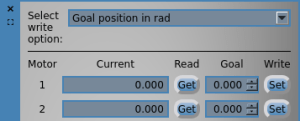
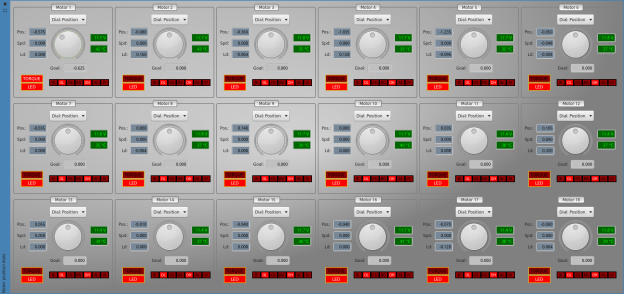
New motor control table value editor

On the GUI side of things, I’ve made a new “motor address editor” as an improvement on the previous “motor value editor”. The new editor allows reading/writing of all control table addresses of the AX-12. You don’t have to worry about writing low/high bytes to the two-byte values, as that is handled by the editor; simply write any valid value to the parameter of interest.

I have kept the old editor as two useful features it has is let me easily write the same value to all motors, as well as send position/speed/torque in “standard” units (rad, rad/s and torque %) instead of raw values.


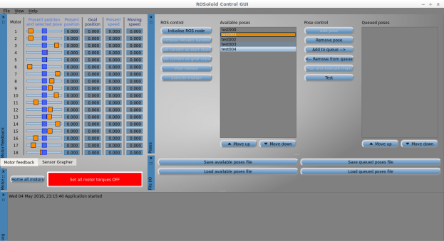
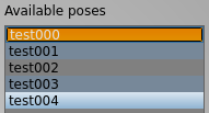
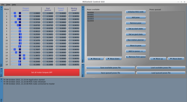
Recording and executing poses

I added a new test function which moves the robot through a sequence of queued poses that are saved in the GUI. The robot pauses between each sequence based on each pose’s specified delay time.

Because the function’s execution has to pause and wait for the specified dwell time time, I added the code into a separate thread. Originally I did this by subclassing QThread, but then updated it and created a “worker object” which is moved to a thread using moveToThread(), as this seems to be the better way in Qt.

Although this is very simplistic motion editor functionality which has been done many times before by other tools, I thought it would be useful to add to my GUI, as it could prove useful in the future as a complement or even a replacement of the MoveIt! ideas if they don’t work out. This GUI is now essentially a one-stop shop for easily testing various ROS functionality and other ideas as I keep on developing along the way!

Further integration with MoveIt!

The integration of the Bioloid with MoveIt! has reached an important milestone, with the real robot now being able to respond to MoveIt! planned trajectories! There’s still a lot to do to improve performance, but the basic framework is ready. In the next few paragraphs I will try to describe the MoveIt! configuration process up to now.

In a previous post I mentioned how the SRDF file was created as the fist step to configuring the robot to use MoveIt! The joint_state_publisher was already set up to publish the values of the joint states, which it read from my AX-12+ motor controller, so RViz was able to display the current state of the robot’s joints live when connected to the robot. Commands could also be sent to move the robot servo’s (such as those sent by the control GUI), but this was done using my own custom ROS services. The link to closing the loop between MoveIt! and the robot was to make MoveIt! able to command motor movement.


The joint controllers

Some background reading quickly led to the tutorial page on controller configuration. In trying to figure out how to first make my AX-12+motor controller provide the required FollowJointTrajectory action, I first looked at the wiki of the actionlib stack and used a C++ SimpleActionServer. However this would mean having to then implement the trajectory following, something which is already by the ROS joint_trajectory_controller package. So instead I looked into how I could get the robot to use this controller, which to lead to reading about ros_control and a very good tutorial from Gazebo. It took some time to understand how all these packages work together, and finally found that I had to implement the hardware_interface for my AX-12+ motor controller. The biggest challenge was figuring out how to configure the controller YAML files and actually get the controller_manager to spawn the controllers correctly.

I have used various roslaunch files and configuration files that set up and run the joint controllers, which I will upload shortly onto my GitHub page, along with updates to the C++ ROS AX-12+ motor controller.

The connections between the various ROS nodes and topics have now grown quite a bit in complexity, compared to the initial ROS interconnections, and now look something like this (captured using rqt_graph):

rqt_graph_control_moveit_and_gui_2015-11-03


Useful links

I have put together a list of links, mostly from the ROS answers site, which were very helpful in getting the controllers to finally work:

Control GUI updates

Progress is going well with my Qt control GUI. The main updates are:

  • New button to cut torque on all motors.
  • New motor value editor, used for writing to the servo control table addresses. The address of choice can be selected, and a value can be set to an individual servo or to all servos at once, using the broadcast ID (254). Also included are three custom functions which write position/speed or torque using more intuitive values: radians, rad/sec or % torque respectively.
  • New position dials for directly controlling the position of each motor.
  • In order to control and receive feedback from the motors, all these GUI functions interface with the ROS publish/subscribe mechanism or ROS services, which my custom usb2ax_controller ROS package is providing in its own separate ROS node.
  • I have been playing around with Qt style sheets to customise the GUI’s main elements such as background, buttons etc.. This was fairly time consuming but overall I think it improves the overall look and feel rather than just having standard grey boxes! I have also used QDockWidget to make various parts of the GUI easy to hide/show, pop out or dock and resize. This seems much more flexible than putting all widgets on one form, or using multiple standard windows or even tabbed windows.

Now the foundations are laid, it’s time to delve deeper into MoveIt!

Robot control GUI first steps

I have switched focus to software at the moment, and am writing a basic user interface that will let me interact with the servo controller and the ROS packages, specifically the MoveIt! Move Group Interface/C++ API.

The interface is written in Qt using the Qt Creator IDE. As this is very ROS focused, I am building the GUI as a ROS package using catkin_make, which was tricky to set up inside Qt Creator, but worked in the end!

Screenshot from 2015-09-22 23-45-47

Currently the GUI can start a ROS node and receive current and goal position/velocity for each servo. It also enables the creation of a list of joint poses from the current robot’s state, and the ability to add them to a second list, which will act as a queue for moving through sequences of poses later on. The lists can be manipulated and also saved/loaded to CSV text files. A group of slider widgets shows the robot’s current joint positions, with added markers to show ‘target’ positions.

A number of buttons are yet not implemented, but the idea is to make this a quick and easy interface to a number of motion plans using the MoveIt! API, as I found it cumbersome trying to test with just a simple test C++ file. Hopefully this is the first step to a GUI with many features to come!

All source code is available on GitHub if you want to have a look.

Robot VR model updates

The robot model has got a small update to make it better resemble its real counterpart rather than the default Bioloid humanoid.

I have also had some success testing the Move Group Interface/C++ API with the robot, as well as managed to start a Qt widgets project using ROS’s CMake build system. This is in its very early stages right now, but will form the basis for further tests and advanced motions with the MoveIt! package.