Tag Archives: 3D printing

Software updates

Here is a quick update on current progress with the software:

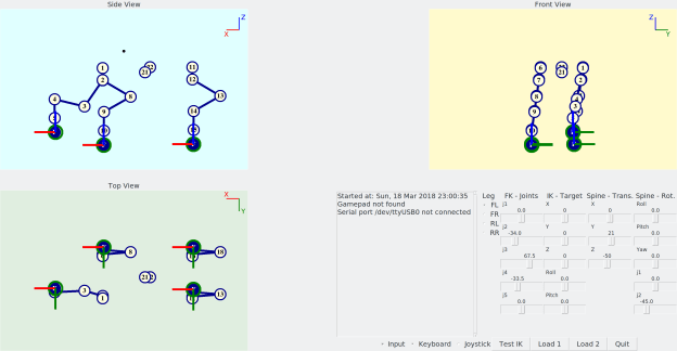
  • The robot spine can now be fully translated and rotated w.r.t. the world frame. Although I mentioned in the past that this isn’t really needed until the issue of localisation is faced, it is actually useful as a testing method for the IK, as all the legs can are moving w.r.t. the base – imagine e.g. the robot moving from a crouching to standing position.
  • The spine RPY orientation in space and its two joints are temporarily set up to influence each other, such that they emulate how the robot would behave if we wanted the spine/body orientation to change while keeping the feet flat – assuming the robot is standing on a perfectly flat surface. This should all make sense once I test the body orientation kinematics on the real robot soon!
  • As the controller I have been using does not work wirelessly, it’s not convenient to always have plugged in, so I added the ability for the test program to read the keyboard input as an alternative for moving the foot target positions. The Python module used is pynput. On this issue of the controller, if anyone knows how to get an XBox One controller’s wireless adaptor to work in Linux and Python, please let me know!
  • The monolithic Python test script was becoming a bit out of hand in terms of size and use of globals, so I’ve broken up into a few separate files and classes with better encapsulation than originally. It’s not perfect or optimised, but a bit more manageable now.

Quadbot 17 Spine XYZ and KB Input

Latest test program, with keyboard input and full spine control.

QB17QuadKinematics01

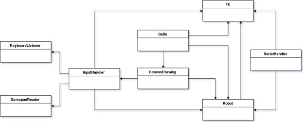
Simple class diagram of the Python program, after refactoring the original single-file script.


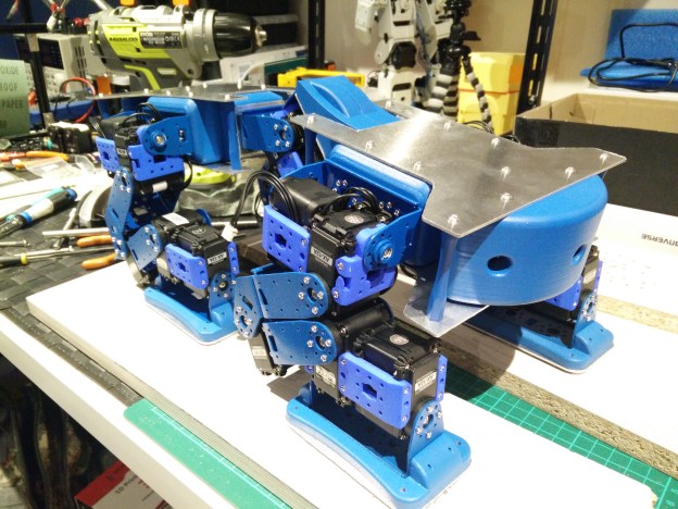
On the hardware side, I have some new controllers to explore various ideas, namely a Robotis OpenCM9.04 and a Raspberry Pi 3. The Raspberry could be mounted to the robot with a 3D-printed case like this.

Chassis assembled

After 3D printing a few more plastic parts and cutting all the aluminium plates, the custom chassis is finally complete! Below are some quick notes on the progress over the last weeks.

More 3D printed parts and painting

I printed off some of the remaining parts of the chassis. The battery compartment was best printed upright with minimal support structure needed. The rear bumper was trickier than the front bumper, because of the additional hole space for the battery, so I found it was best to print upright, with a raft and curved supports at the bottom.

Once all parts were printed, and some more sanding, I spray-painted all the parts with plastic primer, then blue paint, and finally clear sealer.


Metal parts

I was initially thinking of finding an online service to cut out the aluminium chassis parts, but then decided it would be faster and cheaper to just get some sheets 1.5 mm thick aluminium sheets from eBay and cut them on a jigsaw table.
I used Fusion 360’s drawing tool to export to PDF the parts I needed to cut out: four chassis plates and four foot plates. I then printed them in actual scale and glued them on the aluminium to uses as traces.


Assembly

I threaded the holes on all the 3D parts, which were either 3 mm wide where the aluminium plates attach, or 2 mm at the leg and spine bracket attachment points.
Using a tap for the 3 mm holes worked pretty well, but the 2 mm holes were more prone to being stripped or too loose, so manually threading the holes with the bolts worked better. Another issue was the infill surrounding the internal thread cylinder sometimes being a bit too thin. In retrospect, I’d try designing the 3D parts to use heat-set or expandable inserts, especially for the smaller threads.

The servo brackets attaching to the chassis have a large number of holes (16 for each leg and one of the spine brackets, and 12 for the other spine bracket) so the screws so far seem to secure the brackets well enough. The spine section is under a lot of stress from the wight of the whole chassis and legs, so it will not be able to withstand much twisting force, and the servos may not be strong enough at this area, but I will have to test this in practice with new walking gaits.


Conclusions

The custom chassis has finally made it from a 3D design to a reality, with relative success so far. Some of the threaded holes on the 3D parts are not as strong as I’d like, the AX-12 may be under-powered for the spine connection, and the brackets anchoring the spine may be the first to give way due to twisting forces. Also the chassis as a whole would benefit form weight-saving exercise and perhaps being thinned down. But this has only been the first iteration of the main chassis, and the robot design has now become a reality and seems to stand up well. The next step will see how it performs some of the basic walking gaits!


From paper to plastic

… or more correctly, from CAD to reality, as it is time for 3D printing!

I’ve recently got a new 3D printer in the form of a FlashForge Creator Pro 2017, which means I can start printing some of the structural components for the quadruped now, leaving the decorative pieces for later. In fact, some of them have already been printed, as you can see in the images below.


Chassis parts

All the parts were recently updated from their previous iteration slightly, by adding fillets around the edges, and decreasing nut hole diameters by 0.2 mm in order to provide some material for self-tapping threads. On the other hand, I increased the tolerance of some slots by the same amount, to allow a tolerance for their connection to interlocking plastic tabs.

The rear section has also been modified: the underside aluminium base will have a tab at 90° that connects to the rear, to provide more rigidity to the central connection with the spine servo bracket.

Here are the CAD models of the chassis parts:

Foot base

Front body assembly

Rear body assembly


Printing

All parts were printed in PLA plastic.

The first part I started with was the foot base. I printed it with a 20% honeycomb infill. I didn’t add any intermediate solid layers, but might do so in other parts. I have so far printed two out of the four bases.

Each leg will connect to a leg base bracket, which is the same design for all legs. The part was printed “upside-down” because of the orientation of the interlocking tabs. This meant that some support structure was needed for the holes. For the first print attempt I also added supports around the overhang of the filleted edge, along with a brim, but for the subsequent prints I didn’t bother with these, as the fillet overhang held fine without supports, and saved from extra filing/sanding down. These parts also used 20% infill.

For the front and rear “bumpers”, I reduced the infill to 10%.

For the larger part comprising of the central section of the front, the spine front bracket, I also used an infill of 10%. Due to the more complicated design that would have included many overhangs, I found it easier to cut the part lengthwise and print it as two separate pieces. These will be super-glued together after sanding.

Time-lapse GIFs and images of the printing process:


The parts so far

In terms of printing times, the foot bases and leg base brackets took about 3 hours each, the bumpers took around 4 hours each, and the two spine front bracket halves took about 7 hours combined, so total printing time is going to be fairly large!

The 0.2 mm clearance seems to work fine for self-threading the plastic with M2 size metal nuts, but was too large for some of the plastic-to-plastic interlocking tabs, possibly since this tolerance is close to the resolution limits of the printer (theoretically a 0.4 mm nozzle and 0.18 mm layer height). However after some filing and sanding down, all the plastic parts fit together nicely.

The resulting 3D prints before and after sanding:


The assembly so far

Finally, here are some images of how the chassis assembly is shaping up, as well as the foot bases shown attached to the foot metal brackets. These fitted snug without any sanding, and all the holes aligned perfectly with the metal brackets, which was reassuring!


The next step is to glue the front bracket halves together, and maybe spray paint all the parts, as they lose all their original shine and end up looking very scratched after sanding.


Backpack printed

The backpack print from Shapeways has arrived!

Overall I am very pleased with the quality of the print. The walls are only 1.22 mm thick which makes the design somewhat delicate with the standard plastic material, so if I had to print it again I would thicken them. The dimensions perfectly match the screws, battery and back of robot chest, so the backpack fits in without any problems. I should have also added a few more holes around the sides, as the wiring is fairly cramped. The battery cabling is fairly awkward, maybe I should have gone with an even smaller one than originally planned!

Along with the battery, the backpack also houses the SMPS2Dynamixel servo power adaptor and a bunch of wiring. The power adaptor has a tricky shape with servo connectors at a right angle to the DC jack, but I was able to use a smaller plug with its plastic casing removed in order to fit it inside the limited space.

Hopefully the battery is close enough to the centre of mass, and not too high, so it remains to be seen if the servos are powerful enough to keep the robot standing and moving upright. Now it is back to software, to get the robot to finally do some interesting moves!

New Bioloid backpack

Adding to the endless stream of distractions from the main programming, I decided that the current mess of wiring and components on the back of the Bioloid needed tidying up properly. So, I have made a 3D model for a backpack, and I’m waiting for it to be 3D printed at Shapeways. The dimensions are similar to those of the original case which held the CM-5. The two large holes on the sides are for slotting in the new 2200 mAh battery, as it was too big to fit within the backpack.