Tag Archives: kinematics

Walking gait smoothing and tuning

I added some exponential smoothing to the original walking gaits, to smooth the edges of the trajectories and create a more natural movement.

I then added a ±30° pitching motion to what best approximates the ‘ankle’ (4th joint), to emulate the heel off and heel strike phases of the gait cycle.

b9780323039895000213_f014-019-9780323039895

The range of motion of the right ankle joint. Source: Clinical Gate.


I realised however that applying the pitch to the foot target is not exactly the same as applying the pitch to the ankle joint. This is because, in the robot’s case, the ‘foot target’ is located at the centre of the lowest part of the foot, that comes into contact with the ground, whereas the ankle is higher up, at a distance of two link lengths (in terms of the kinematics, that’s a4+a5). The walking gait thus does not ends up producing the expected result (this is best explained by the animations are the end).

To account for this, I simply had to adjust the forward/backward and up/down position of the target, in response to the required pitch.

With some simple trigonometry, the fwd/back motion is adjusted by -A*sin(pitch), while the up/down motion is adjusted by +A*(1-cos(pitch)), where A is the distance a4+a5 noted previously.

Here are the details showing how the targets are adjusted for one particular phase in the creep walk gait (numbers involving translations are all normalised because of the way the gait code currently works):

Pitch Adjustments Graph

Creep walk gait, 25-step window where the foot target pitch oscillates between ±30°. Original target translations (fwd/back, up/down) are shown compared to the ones adjusted in response to the pitch.


The final results of the foot pitching, with and without smoothing, are shown below:

This slideshow requires JavaScript.

This slideshow requires JavaScript.

This slideshow requires JavaScript.


Steering input adjustments

Following on from the previous post on walking and steering, I realised that when moving the spine joints, the rear feet remain anchored to the ground, when it would be better if they rotated around the spine motors, to give a better turning circle for steering.

The reason behind why the feet remain fixed is because their targets are being defined in world coordinate space, so moving the spine won’t change the target.

There are advantages to defining the targets in world space for future work, when the robot knows more information about its environment. For example the legs can be positioned in the world in order to navigate upcoming terrain or obstacles. But for now, it is often useful to work in coordinates local to the base (front base for front legs, and rear base for rear legs), since in this way you don’t have to worry about the relative positioning of the front base w.r.t. rear.

I will eventually update the kinematics code so either world or local targets can be selected.

For now however, I have made an update to the code, so if the spine joint sliders, gaits or walking/steering inputs are used, the rear leg targets move with the spine. To explain this better visually:

This slideshow requires JavaScript.

Another minor adjustment you might notice was the widening of the stance, to provide a larger support polygon. The walking gaits still need fine-tuning, as walking on the actual robot is still unstable and slow.


Body Moving

New video!

I have been testing the movement of the robot’s base in the world, while keeping the legs fixed to the ground, as a test of the robot’s stability and flexibility.

The robot base can now be controlled, either via the GUI, keyboard or gamepad, in the following ways:

  • Translation in XYZ
  • Roll/pitch/yaw
  • Movement of the two spine joints – Front of robot remains still, while rear adjusts
  • Movement of the two spine joints – Front of robot attempts to counteract the motion of the rear

You may notice the real robot can’t move its upper leg all the way horizontally as the IK might suggest is possible, because there is a small clash between the AX-12 and the metal bracket, but this should be fixed by filing or bending the curved metal tabs:

Leg Clash Check - CAD-Actual.png


Software updates

I have recently written an OpenCM sketch to control the robot servos, in a way similar to how it was being done with the older Arbotix-M, but this time using the Robotis libraries for communicating with the motors.

I have also been making various updates to the Python test code, with a few of the main issues being:

  • Improved the code for positioning the base and base target in world
  • Updated base/spine transforms – Front legs now move with base, not first spine joint
  • Fixed the leg IK – Legs now remain in line with ground when the base moves
  • Added new keyboard/joystick input modes for controlling base position, base orientation, spine joints
  • Updated the serial string sending function and fixed some minor issues
  • Moved a load of script configuration variables to a separate Params module
  • Added a combo box to the GUI front-end for loading a selection of CSV files (as an update to the previous two fixed buttons)

All the latest code can be found on the Quadbot17 GitHub project page as usual.

Software updates

Here is a quick update on current progress with the software:

  • The robot spine can now be fully translated and rotated w.r.t. the world frame. Although I mentioned in the past that this isn’t really needed until the issue of localisation is faced, it is actually useful as a testing method for the IK, as all the legs can are moving w.r.t. the base – imagine e.g. the robot moving from a crouching to standing position.
  • The spine RPY orientation in space and its two joints are temporarily set up to influence each other, such that they emulate how the robot would behave if we wanted the spine/body orientation to change while keeping the feet flat – assuming the robot is standing on a perfectly flat surface. This should all make sense once I test the body orientation kinematics on the real robot soon!
  • As the controller I have been using does not work wirelessly, it’s not convenient to always have plugged in, so I added the ability for the test program to read the keyboard input as an alternative for moving the foot target positions. The Python module used is pynput. On this issue of the controller, if anyone knows how to get an XBox One controller’s wireless adaptor to work in Linux and Python, please let me know!
  • The monolithic Python test script was becoming a bit out of hand in terms of size and use of globals, so I’ve broken up into a few separate files and classes with better encapsulation than originally. It’s not perfect or optimised, but a bit more manageable now.

Quadbot 17 Spine XYZ and KB Input

Latest test program, with keyboard input and full spine control.

QB17QuadKinematics01

Simple class diagram of the Python program, after refactoring the original single-file script.


On the hardware side, I have some new controllers to explore various ideas, namely a Robotis OpenCM9.04 and a Raspberry Pi 3. The Raspberry could be mounted to the robot with a 3D-printed case like this.

Body/spine and improved leg kinematics

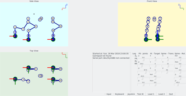
The Python test program has been updated to include the additional spine joints, transformation between the robot and world coordinates, and leg targets which take orientation into account.

This test script is used in anticipation for controlling the actual robot’s servos.
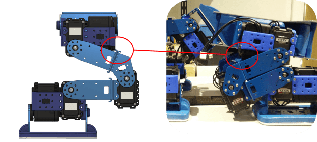


Spine joints

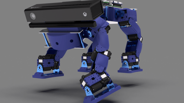
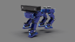
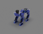
The “spine” consists of two joints which will allow the front of the robot to pitch and yaw independently of the rear. This will give it more flexibility when turning and handling uneven terrain, as well as other tasks such as aiming its sensors at the world.

Since the spine joints are quite simple, I don’t think there is any need to create IK for this section.


Main Assembly v114 Spine

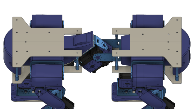
The “spine” joints separate the body of the quadruped between mostly similar front and rear sections.


Body and spine orientation

The robot body now takes into account that it has to be oriented w.r.t. the “world”. This will be physically achieved by the information acquired by an IMU sensor. If the robot is tilted forwards, the targets for the legs will have to be adjusted so that the robot maintains its balance.

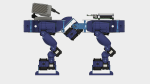
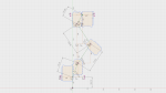
I have defined the kinematics in a way that if the the robot was to rotate w.r.t. the world, the whole body rotates (this can be achieved by moving the test Roll/Pitch/Yaw sliders). However if the servo joints of the spine are moved (test joint 1 / joint 2 sliders) the rear section of the robot will move w.r.t the world, and the rear legs will move with it, while the front section won’t change w.r.t. the world.

In order to achieve this, the leg IK had to be updated so that now the base frames of the front legs are linked to the front section of the robot, and the base frames of the rear legs are linked to the rear section.

You might notice while orientation will be defined by an IMU, pure translation (movement in XYZ) in the world is not considered for now, as it is meaningless without some sort of localisation capability in place. This could be achieved by a sensor (see below), but is an entirely separate challenge for a long way down the line (hint: SLAM).

Quadbot 17 Quad Kinematics_004

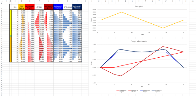
New leg targets: Foot roll/pitch can be attained (within limits). In addition, the robot base can be positioned with respect to an outside world frame.

Quadbot 17 Quad Kinematics_002

Original leg targets: The feet are always pointing vertical to the ground.


Target roll and yaw

Initially, the leg target was simply a position in 3D for the foot link, and the foot was always pointing perpendicular to the ground, which made the inverse kinematics fairly easy. In version 2, the target orientation is now also taken into account. Actually, the pitch and roll can be targeted, but yawing cannot be obtained, simply because of the mechanics of the legs. Yawing, or turning, can be done by changing the walking gait pattern alone,  but the idea is that the spine bend will also aid in steering the robot (how exactly I don’t know yet, but that will come later!).

Getting the kinematics to work were a bit trickier than the original version, mainly because the “pitching” orientation of the leg can only be achieved by the positioning of joint 4, whereas the “rolling” orientation can only be achieved by the positioning of joint 5. The available workspace of the foot is also somewhat limited, in part due to that missing yaw capability. Particularly at positions when the leg has to stretch sideways (laterally) then certain roll/pitching combinations are impossible to reach. Nevertheless, this implementation gives the feet enough freedom to be placed on fairly uneven surfaces, and not be constrained to the previously flat plane.

The next challenge that follows from this, is how can realistic target positions and orientations be generated (beyond predetermined fixed walking gaits), to match what the robot sees of the world?

To answer this, first I need to decide how the robot sees the world: Primarily it will be by means of some 3D scanner, such as the ones I’ve looked into in the past, or maybe the Intel RealSense ZR300 which has recently caught my attention. But this alone might not be sufficient, and some form of contact sensors on the feet may be required.

The big question is, should I get a RealSense sensor for this robot ??? 🙂


Updated code can be found on GitHub (single-file test script is starting to get long, might be time to split up into class files!).


Quadbot updates and sensor options

Updates

A few and bits and pieces have been added to the model, along with some updates: Longer lower leg and cover, battery and battery compartment in rear body, main electronics boards, foot base and plate, and two ideas for sensors.

The lower legs were extended as initially the “knee” and “ankle” joints were too close. I think the new arrangement gives the leg better overall proportions.

As the battery pack has significant size and weight, its best to include in the design as early as possible. Originally neglected, I have now added a Turnigy 2200 mAh battery, and updated the rear bumper and bracket to accommodate it. Heat dissipation may be an issue, but I’ll leave it like this for now.

I have also measured the placement of the actuators in order to start thinking about the maths for the kinematics.

Some images of current progress:


Sensors

I have tried two ideas for area scanners which could be the main “eyes” of the robot. One is the Kinect v2, and the other a Scanse Sweep.

The main advantages of the Sweep is that it is designed specifically for robotics, with a large range and operation at varying light levels. On its own it only scans in a plane by spinning 360°, however it can be turned into a spherical scanner with little effort. Added bonuses are a spherical scan mounting bracket designed specifically for Dynamixel servos, as well as ROS drivers! It is currently available only on pre-order on SparkFun.

The Kinect has a good resolution and is focused on tracking human subjects, being able to track 6 complete skeletons and 25 joints per person. However it only works optimally indoors and at short ranges directly in front of it. It is however significantly cheaper than the Sweep.

Below is a table comparing the important specs:

XBOX Kinect v2

Scanse Sweep

Technology

Time-of-Flight

LiDAR

Dimensions (mm)

249 x 66 x 67

65 x 65 x 52.8

Weight (kg)

1.4

0.12

Minimum Range (m)

0.5

~0.1

Maximum Range (m)

4.5

40

Sample rate (Hz)

30

1000

Rotation rate (Hz)

N/A

1-10

FOV (°)

70 x 60

360 (planar)

Resolution

512 x 424, ~ 7 x 7 pixels per °

1 cm

Price (£)

280

80 (32 for adaptor)

Sources:


WordPress tip: One thing I really like about WordPress.com is that there are always ways around doing things that initially only seem possible with WordPress.org. Need to add a table into your post? Use Open Live Writer, make the table then copy-paste the table’s generated HTML source code!


Hardware costs

The current estimated hardware costs are quite high, at around £2100. However about half this budget (£955) is due to the fact that I calculated the costs for the custom 3D printed parts by getting quotes from Shapeways. Getting them printed on a homemade 3D printer would reduce the cost significantly. The other large cost is naturally the 22 AX actuators at £790.

For anyone interested, the preliminary BOM can be downloaded here:

Quadbot 17 BOM – 2017-02-26.xlsx


That’s it for now!