Here is a quick update on current progress with the software:
The robot spine can now be fully translated and rotated w.r.t. the world frame. Although I mentioned in the past that this isn’t really needed until the issue of localisation is faced, it is actually useful as a testing method for the IK, as all the legs can are moving w.r.t. the base – imagine e.g. the robot moving from a crouching to standing position.
The spine RPY orientation in space and its two joints are temporarily set up to influence each other, such that they emulate how the robot would behave if we wanted the spine/body orientation to change while keeping the feet flat – assuming the robot is standing on a perfectly flat surface. This should all make sense once I test the body orientation kinematics on the real robot soon!
As the controller I have been using does not work wirelessly, it’s not convenient to always have plugged in, so I added the ability for the test program to read the keyboard input as an alternative for moving the foot target positions. The Python module used is pynput. On this issue of the controller, if anyone knows how to get an XBox One controller’s wireless adaptor to work in Linux and Python, please let me know!
The monolithic Python test script was becoming a bit out of hand in terms of size and use of globals, so I’ve broken up into a few separate files and classes with better encapsulation than originally. It’s not perfect or optimised, but a bit more manageable now.
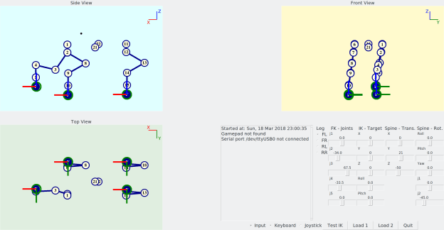
Latest test program, with keyboard input and full spine control.
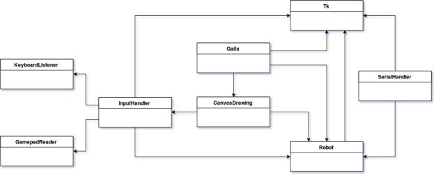
Simple class diagram of the Python program, after refactoring the original single-file script.
On the hardware side, I have some new controllers to explore various ideas, namely a Robotis OpenCM9.04 and a Raspberry Pi 3. The Raspberry could be mounted to the robot with a 3D-printed case like this.
The Python test program has been updated to include the additional spine joints, transformation between the robot and world coordinates, and leg targets which take orientation into account.
This test script is used in anticipation for controlling the actual robot’s servos.
Spine joints
The “spine” consists of two joints which will allow the front of the robot to pitch and yaw independently of the rear. This will give it more flexibility when turning and handling uneven terrain, as well as other tasks such as aiming its sensors at the world.
Since the spine joints are quite simple, I don’t think there is any need to create IK for this section.
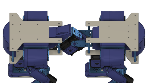
The “spine” joints separate the body of the quadruped between mostly similar front and rear sections.
Body and spine orientation
The robot body now takes into account that it has to be oriented w.r.t. the “world”. This will be physically achieved by the information acquired by an IMU sensor. If the robot is tilted forwards, the targets for the legs will have to be adjusted so that the robot maintains its balance.
I have defined the kinematics in a way that if the the robot was to rotate w.r.t. the world, the whole body rotates (this can be achieved by moving the test Roll/Pitch/Yaw sliders). However if the servo joints of the spine are moved (test joint 1 / joint 2 sliders) the rear section of the robot will move w.r.t the world, and the rear legs will move with it, while the front section won’t change w.r.t. the world.
In order to achieve this, the leg IK had to be updated so that now the base frames of the front legs are linked to the front section of the robot, and the base frames of the rear legs are linked to the rear section.
You might notice while orientation will be defined by an IMU, pure translation (movement in XYZ) in the world is not considered for now, as it is meaningless without some sort of localisation capability in place. This could be achieved by a sensor (see below), but is an entirely separate challenge for a long way down the line (hint: SLAM).
New leg targets: Foot roll/pitch can be attained (within limits). In addition, the robot base can be positioned with respect to an outside world frame.
Original leg targets: The feet are always pointing vertical to the ground.
Target roll and yaw
Initially, the leg target was simply a position in 3D for the foot link, and the foot was always pointing perpendicular to the ground, which made the inverse kinematics fairly easy. In version 2, the target orientation is now also taken into account. Actually, the pitch and roll can be targeted, but yawing cannot be obtained, simply because of the mechanics of the legs. Yawing, or turning, can be done by changing the walking gait pattern alone, but the idea is that the spine bend will also aid in steering the robot (how exactly I don’t know yet, but that will come later!).
Getting the kinematics to work were a bit trickier than the original version, mainly because the “pitching” orientation of the leg can only be achieved by the positioning of joint 4, whereas the “rolling” orientation can only be achieved by the positioning of joint 5. The available workspace of the foot is also somewhat limited, in part due to that missing yaw capability. Particularly at positions when the leg has to stretch sideways (laterally) then certain roll/pitching combinations are impossible to reach. Nevertheless, this implementation gives the feet enough freedom to be placed on fairly uneven surfaces, and not be constrained to the previously flat plane.
The next challenge that follows from this, is how can realistic target positions and orientations be generated (beyond predetermined fixed walking gaits), to match what the robot sees of the world?
To answer this, first I need to decide how the robot sees the world: Primarily it will be by means of some 3D scanner, such as the ones I’ve looked into in the past, or maybe the Intel RealSense ZR300 which has recently caught my attention. But this alone might not be sufficient, and some form of contact sensors on the feet may be required.
The big question is, should I get a RealSense sensor for this robot ??? 🙂
Updated code can be found on GitHub (single-file test script is starting to get long, might be time to split up into class files!).
After realising in my previous post that solving the gimbal lock problem for the complementary filter requires fiddly and inelegant fixes, I decided to dive into the world of quaternions. Luckily, the theory behind quaternions doesn’t need to be fully understood, in order to use them to represent 3D rotations. Particularly useful are the conversions between quaternion and rotation matrix, and axis-angle representation.
I initially tried to make the Arduino MCU (A-Star) perform the filtering process and pass the IMU frame transform to the PC, however this presented a couple of issues, the first being that there is no standard vector and matrix library in Arduino. Second, although I could write a very simple library for vector cross and dot products etc., the MCU’s 32 KB of flash memory was already almost full with all the rosserial and IMU libraries, leaving little space for anything else.
Hence I opted for letting the MCU simply pass a number of ROS message streams over to the PC, which could then do the required transformations using the ROS tf library. The Arduino code is listed at the end of this post (bioloid_sensors.ino).
Pololu A-Star 32U4 Mini SV
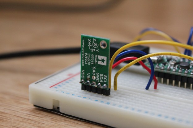
Pololu MinIMU-9 v3
The MCU reads the MinIMU-9 v3 IMU data and publishes it as ROS messages on the following topics:
LSM303 accelerometer x, y, z values (“accel”)
LSM303 magnetometer x, y, z values (“magnet”)
L3G gyroscope x, y, z values (“gyro”)
LSM303 magnetometer heading value (“heading”), derived from the LSM303’s library, as the angular difference in the horizontal plane between the x axis and magnetic North
ROS has a very handy plotting tool for topics, called rqt_plot. Below is an example dump of all the IMU data.
IMU messages plotted in rqt_plot
Quaternion-based filter
Having spent too much time on the RPY approach already, I wanted to find a simple way to achieve a relatively stable orientation from the IMU readings. I ended up implementing the method from this AHRS maths tutorial from the Firetail UAV system. The method is explained very well in that link, so there is no need to go into the details. The only change I have made is in the calculation of the filter coefficient, based on a set time constant as was done previously. My version using a ROS subscriber on the PC side is again listed at the end of this post (imu_tf_broadcaster.cpp and .h files).
Videos
Here are two videos comparing the original RPY approach against the improved quaternion approach. The resulting IMU transform is published by tf, which is used by the robot model you see in RViz, the ROS visualisation tool. The model is generated using a URDF file; I will explain this in detail in a following post.
Although in both cases the rotation is fairly smooth, you can see the problems that the RPY filtering encounters when it nears the gimbal lock position (when the robot lies horizontally). For my purposes of orientating the robot, I think the current quaternion approach is perfectly suited. I doubt I will be needing to play around with Kalman filters and the likes, as I currently don’t need the precision that UAVs etc. may need!
So that’s it for IMUs and orientation for the time being. In my next post I will start detailing the current progress with the virtual bioloid in ROS, which was seen in the above videos.
Code (click to expand):
// Hardware:
// Pololu A-Star 32U4 Mini SV
// Pololu MinIMU-9 v3 (L3GD20H and LSM303D)
// Interlink FSR 400 Short (x6)

// Important! Define this before #include <ros.h>
#define USE_USBCON

#include <Wire.h>
#include <ros.h>
#include <std_msgs/Int16MultiArray.h>
#include <geometry_msgs/Vector3.h>
#include <std_msgs/Float32.h>
#include <AStar32U4Prime.h>
#include <LSM303.h>
#include <L3G.h>

// Set up the ros node and publishers
ros::NodeHandle nh;
std_msgs::Int16MultiArray msg_fsrs;
std_msgs::MultiArrayDimension fsrsDim;
ros::Publisher pub_fsrs("fsrs", &msg_fsrs);
geometry_msgs::Vector3 msg_accel;
ros::Publisher pub_accel("accel", &msg_accel);
geometry_msgs::Vector3 msg_magnet;
ros::Publisher pub_magnet("magnet", &msg_magnet);
std_msgs::Float32 msg_heading;
ros::Publisher pub_heading("heading", &msg_heading);
geometry_msgs::Vector3 msg_gyro;
ros::Publisher pub_gyro("gyro", &msg_gyro);
unsigned long pubTimer = 0;

const int numOfFSRs = 6;
const int FSRPins[] = {A0, A1, A2, A3, A4, A5};
int FSRValue = 0;
LSM303 compass;
L3G gyro;
const int yellowLEDPin = IO_C7;  // 13
int LEDBright = 0;
int LEDDim = 5;
unsigned long LEDTimer = 0;

void setup()
{
    // Array for FSRs
    msg_fsrs.layout.dim = &fsrsDim;
    msg_fsrs.layout.dim[0].label = "fsrs";
    msg_fsrs.layout.dim[0].size = numOfFSRs;
    msg_fsrs.layout.dim[0].stride = 1*numOfFSRs;
    msg_fsrs.layout.dim_length = 1;
    msg_fsrs.layout.data_offset = 0;
    msg_fsrs.data_length = numOfFSRs;
    msg_fsrs.data = (int16_t *)malloc(sizeof(int16_t)*numOfFSRs);

    nh.initNode();
    nh.advertise(pub_fsrs);
    nh.advertise(pub_accel);
    nh.advertise(pub_magnet);
    nh.advertise(pub_heading);
    nh.advertise(pub_gyro);

    // Wait until connected
    while (!nh.connected())
        nh.spinOnce();
    nh.loginfo("ROS startup complete");

    Wire.begin();

    // Enable pullup resistors
    for (int i=0; i<numOfFSRs; ++i)
        pinMode(FSRPins[i], INPUT_PULLUP);

    if (!compass.init())
    {
        nh.logerror("Failed to autodetect compass type!");
    }
    compass.enableDefault();

    // Compass calibration values
    compass.m_min = (LSM303::vector<int16_t>){-3441, -3292, -2594};
    compass.m_max = (LSM303::vector<int16_t>){+2371, +2361, +2328};

    if (!gyro.init())
    {
        nh.logerror("Failed to autodetect gyro type!");
    }
    gyro.enableDefault();

    pubTimer = millis();
}

void loop()
{
    if (millis() > pubTimer)
    {
        for (int i=0; i<numOfFSRs; ++i)
        {
            FSRValue = analogRead(FSRPins[i]);
            msg_fsrs.data[i] = FSRValue;
            delay(2);  // Delay to allow ADC VRef to settle
        }

        compass.read();
        gyro.read();

        // Compass - accelerometer:
        // 16-bit, default range +-2 g, sensitivity 0.061 mg/digit
        // 1 g = 9.80665 m/s/s
        // e.g. value for z axis in m/s/s will be: compass.a.z * 0.061 / 1000.0 * 9.80665
        //      value for z axis in g will be: compass.a.z * 0.061 / 1000.0
        // Gravity is measured as an upward acceleration:
        // Stationary accel. shows +1 g value on axis facing directly "upwards"
        // Convert values to g
        msg_accel.x = (float)(compass.a.x)*0.061/1000.0;
        msg_accel.y = (float)(compass.a.y)*0.061/1000.0;
        msg_accel.z = (float)(compass.a.z)*0.061/1000.0;

        // Compass - magnetometer:
        // 16-bit, default range +-2 gauss, sensitivity 0.080 mgauss/digit
        msg_magnet.x = (float)(compass.m.x);
        msg_magnet.y = (float)(compass.m.y);
        msg_magnet.z = (float)(compass.m.z);
        // Heading from the LSM303D library is the angular difference in
        // the horizontal plane between the x axis and North, in degrees.
        // Convert value to rads, and change range to +-pi
        msg_heading.data = ( (float)(compass.heading())*M_PI/180.0 );

        // Gyro:
        // 16-bit, default range +-245 dps (deg/sec), sensitivity 8.75 mdps/digit
        // Convert values to rads/sec
        msg_gyro.x = (float)(gyro.g.x)*0.00875*M_PI/180.0;
        msg_gyro.y = (float)(gyro.g.y)*0.00875*M_PI/180.0;
        msg_gyro.z = (float)(gyro.g.z)*0.00875*M_PI/180.0;

        pub_fsrs.publish(&msg_fsrs);
        pub_accel.publish(&msg_accel);
        pub_magnet.publish(&msg_magnet);
        pub_heading.publish(&msg_heading);
        pub_gyro.publish(&msg_gyro);

        pubTimer = millis() + 10;  // wait at least 10 msecs between publishing
    }

    // Pulse the LED
    if (millis() > LEDTimer)
    {
        LEDBright += LEDDim;
        analogWrite(yellowLEDPin, LEDBright);
        if (LEDBright == 0 || LEDBright == 255)
            LEDDim = -LEDDim;

        // 50 msec increments, 2 sec wait after each full cycle
        if (LEDBright != 0)
            LEDTimer = millis() + 50;
        else
            LEDTimer = millis() + 2000;
    }

    nh.spinOnce();
}
#include "imu_tf_broadcaster.h"

int main(int argc, char **argv)
{
    ros::init(argc, argv, "imu_tf_broadcaster");
    ros::NodeHandle n;
    ros::Rate loop_rate(1000);  // Hz

    Broadcaster broadcaster;

    ros::Subscriber accelSub   = n.subscribe("accel",   1000, &Broadcaster::accelCallback,   &broadcaster);
    ros::Subscriber magnetSub  = n.subscribe("magnet",  1000, &Broadcaster::magnetCallback,  &broadcaster);
    ros::Subscriber headingSub = n.subscribe("heading", 1000, &Broadcaster::headingCallback, &broadcaster);
    ros::Subscriber gyroSub    = n.subscribe("gyro",    1000, &Broadcaster::gyroCallback,    &broadcaster);

    while(n.ok())
    {
        //broadcaster.updateTimers();
        //broadcaster.updateRotation();
        broadcaster.tfBroadcaster->sendTransform(
            tf::StampedTransform(
                tf::Transform(broadcaster.getQ(), tf::Vector3(0.0, 0.0, 0.0)),
                ros::Time::now(),"odom", "imu_link"));
        loop_rate.sleep();
        ros::spinOnce();

//        std::cout << "dt: " << broadcaster.getDt() << std::endl;
//        std::cout << "q.x: " << broadcaster.getQ().x() << std::endl;
//        std::cout << "q.y: " << broadcaster.getQ().y() << std::endl;
//        std::cout << "q.z: " << broadcaster.getQ().z() << std::endl;
//        std::cout << "q.w: " << broadcaster.getQ().w() << std::endl;
//        std::cout << "----" << std::endl;
    }

    return 0;
}

Broadcaster::Broadcaster() :
    prevt(ros::Time::now().toSec()),
    dt(0.0),
    timeConst(1.0),
    filterCoeff(0.0)
{
    q.setRPY(0.0, 0.0, 0.0);
    tfBroadcaster = new tf::TransformBroadcaster();
}

Broadcaster::~Broadcaster()
{

}

void Broadcaster::accelCallback(const geometry_msgs::Vector3::ConstPtr& msg)
{
    accel.setX(msg->x);
    accel.setY(msg->y);
    accel.setZ(msg->z);
}

void Broadcaster::magnetCallback(const geometry_msgs::Vector3::ConstPtr& msg)
{
    magnet.setX(msg->x);
    magnet.setY(msg->y);
    magnet.setZ(msg->z);
}

void Broadcaster::headingCallback(const std_msgs::Float32::ConstPtr& msg)
{
    heading = msg->data;
}

void Broadcaster::gyroCallback(const geometry_msgs::Vector3::ConstPtr& msg)
{
    dt = ros::Time::now().toSec() - prevt;

    gyro.setX(msg->x);
    gyro.setY(msg->y);
    gyro.setZ(msg->z);

    angularVel.setX(gyro.x());
    angularVel.setY(gyro.y());
    angularVel.setZ(gyro.z());

    filterCoeff = timeConst / (timeConst + dt);

    // Use accelerometer and magnetometer data to correct gyro drift
    correctOrientation();

    updateRotation();

    prevt = ros::Time::now().toSec();

//    std::cout << "angularVel x: " << angularVel.x() << std::endl;
//    std::cout << "angularVel y: " << angularVel.y() << std::endl;
//    std::cout << "angularVel z: " << angularVel.z() << std::endl;
//    std::cout << "----" << std::endl;
}

void Broadcaster::updateRotation()
{
    // New quaternion, from axis-angle notation for gyro
    tf::Quaternion qNew(angularVel.normalized(), angularVel.length()*dt);

    // Update previous value
    q *= qNew;
    q.normalize();
}

void Broadcaster::correctOrientation()
{
    // Use acceleration data only if vector is close to 1 g
    if ( fabs(accel.length() - 1) <= 0.1 )
    {
        // These vectors have to be perpendicular.
        // As there is no guarantee that North is perpendicular to Down,
        // set North to the cross product of East and Down.
        // Gravity is measured as an upward acceleration.
        tf::Vector3 Down(accel);  // Should be -accel, but not sure why this produces inverted axes!?
        tf::Vector3 E = Down.cross(magnet);
        tf::Vector3 N = E.cross(Down);

        Down.normalize();
        E.normalize();
        N.normalize();

        // The rows of the rotation matrix represent the coordinates in the original
        // space of unit vectors along the coordinate axes of the rotated space
        tf::Matrix3x3 gyroRotMat = tf::Matrix3x3(q);

        // Correction vector
        tf::Vector3 cv = ( N.cross(gyroRotMat.getRow(0)) +
                           E.cross(gyroRotMat.getRow(1)) +
                           Down.cross(gyroRotMat.getRow(2)) ) * filterCoeff;

        angularVel += cv;
    }
}