
I finally got round to installing the force sensing resistors to the underside of the Bioloid’s feet. I am using the FSR 400 Short model, with male end connectors, which are small and flat and didn’t fit in the square female header pins which often come at the end of breadboard wires. I didn’t want to solder directly as I’ve damaged these sensors in the past, so I followed a suggestion on the Adafruit website and ended up using these PCB terminal blocks.
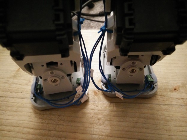
The force sensing element of the FSR fits nicely in the pre-existing cut-out on the underside of the Bioloid foot plate, and the pins are fed through a hole in the plate so they can be connected on the topside. However, in the standard Bioloid humanoid configuration, the foot plates are attached at an offset from the ankle angle brackets, which means there is not enough space between the footplate and the bracket to connect the pins. To fix this, I moved the footplates so that the ankle brackets sit along their centres. There is still some free space between the footplates when the Bioloid sits in its resting position, so hopefully the feet will not collide with each other after this change.
For completeness, I also made changes to the CAD model and also added FSR CAD models to the feet, although that is just a cosmetic addition to the model (on a related side-note, I also found a CAD model of the USB2AX which adds to the realism)! The robot’s URDF files and CAD models have been updated on GitHub.
Here are some pictures of the results:


Pingback: Body/spine and improved leg kinematics | Cognitive Dissonance