

… or more correctly, from CAD to reality, as it is time for 3D printing!
I’ve recently got a new 3D printer in the form of a FlashForge Creator Pro 2017, which means I can start printing some of the structural components for the quadruped now, leaving the decorative pieces for later. In fact, some of them have already been printed, as you can see in the images below.
Chassis parts
All the parts were recently updated from their previous iteration slightly, by adding fillets around the edges, and decreasing nut hole diameters by 0.2 mm in order to provide some material for self-tapping threads. On the other hand, I increased the tolerance of some slots by the same amount, to allow a tolerance for their connection to interlocking plastic tabs.
The rear section has also been modified: the underside aluminium base will have a tab at 90° that connects to the rear, to provide more rigidity to the central connection with the spine servo bracket.
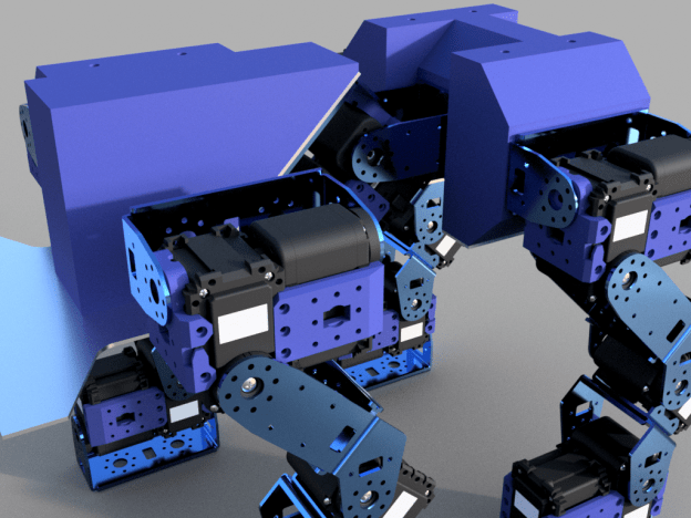
Here are the CAD models of the chassis parts:
Foot base


Front body assembly


Rear body assembly


Printing
All parts were printed in PLA plastic.
The first part I started with was the foot base. I printed it with a 20% honeycomb infill. I didn’t add any intermediate solid layers, but might do so in other parts. I have so far printed two out of the four bases.
Each leg will connect to a leg base bracket, which is the same design for all legs. The part was printed “upside-down” because of the orientation of the interlocking tabs. This meant that some support structure was needed for the holes. For the first print attempt I also added supports around the overhang of the filleted edge, along with a brim, but for the subsequent prints I didn’t bother with these, as the fillet overhang held fine without supports, and saved from extra filing/sanding down. These parts also used 20% infill.
For the front and rear “bumpers”, I reduced the infill to 10%.
For the larger part comprising of the central section of the front, the spine front bracket, I also used an infill of 10%. Due to the more complicated design that would have included many overhangs, I found it easier to cut the part lengthwise and print it as two separate pieces. These will be super-glued together after sanding.
Time-lapse GIFs and images of the printing process:

 854x480")


The parts so far
In terms of printing times, the foot bases and leg base brackets took about 3 hours each, the bumpers took around 4 hours each, and the two spine front bracket halves took about 7 hours combined, so total printing time is going to be fairly large!
The 0.2 mm clearance seems to work fine for self-threading the plastic with M2 size metal nuts, but was too large for some of the plastic-to-plastic interlocking tabs, possibly since this tolerance is close to the resolution limits of the printer (theoretically a 0.4 mm nozzle and 0.18 mm layer height). However after some filing and sanding down, all the plastic parts fit together nicely.
The resulting 3D prints before and after sanding:


The assembly so far
Finally, here are some images of how the chassis assembly is shaping up, as well as the foot bases shown attached to the foot metal brackets. These fitted snug without any sanding, and all the holes aligned perfectly with the metal brackets, which was reassuring!


The next step is to glue the front bracket halves together, and maybe spray paint all the parts, as they lose all their original shine and end up looking very scratched after sanding.


