Extruder
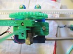
First off, the idler block was attached to the extruder. Simple job and the extruder is almost complete! I’ll return to it again later.

The idler block is attached to the extruder at the top with two long (40 mm) M3 bolts. The hinged bottom pivots on another M3 bolt (need to cut the excess thread or use a more suitable size).
Y-axis assembly
Assembly of the y-axis started by attaching the appropriately sized print bottom plate to the bushings which run along the smooth guiding rods. The bushings were glues onto the plate with two-part epoxy.
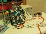
For all five stepper motors, we chose the NEMA 17 SY42STH47-1684B model, which provides the required torque for all axes as well as extruder.
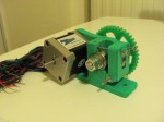
The y-axis motor was attached to the y-bracket on the RepRap frame. The rapid prototyped (RP) pulley was also attached and secured to the motor shaft with an M3 grub nut and hex bolt.

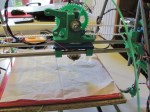
Print bottom plate. The timing belt is secured onto the plate using two RP belt clamps.

Close-up of y-axis motor, pulley and timing belt. The motor is attached to its bracket with three M3x10 mm hex bolts.
You might notice that the motor is mounted on the side of the y-bracket opposite than that shown in the instructions. This is actually because, due to a small hiccup, my y-bracket was printed as a mirror-image of the original STL part (this is also the case for some of the x-axis parts as you’ll see later). The reason I had to mirror the motor position, is because the side of the y-bracket on which the motor should sit has recesses for the M3 hex bolt heads. The M3x10 mm bolts are too short to secure the motor if it’s mounted on the other side. Later on I will simply have to mirror the y-axis movement direction in the control software.
The final step was to mount the timing belt in place using belt clamps and M3x25 mm bolts with washers. Enough tension is needed so that the belt doesn’t sag and the print bottom belt moves smoothly along the guiding rods.
X-axis assembly
As noted previously, the x-axis end parts are also mirror-prints of the originals, hence the assembly will have to be adjusted accordingly. This however shouldn’t have any impact on the functionality of the printer.
The first step was to attach the smooth rods to the x-end parts. Some filing was in order to get the rods to squeeze in. I believe the x-end parts you see here are the versions which use LM8UU metal linear bearings (similar to the ones here), although I will be using RP plastic bearings instead. These RP parts don’t have long channels travelling all the way through them, so the rods can only slide in up to a point. They attach firmly on each side, without the use of M3 bolts. However, this means that the distance between the x-ends is essentially fixed, so later on the z-motor mounts on the top threaded rods will have to be adjusted accordingly.

Smooth rods attached to the x-end-motor and x-end-idler RP parts.

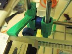
Close-up of the x-idler bearing over which the x-axis timing belt is mounted.

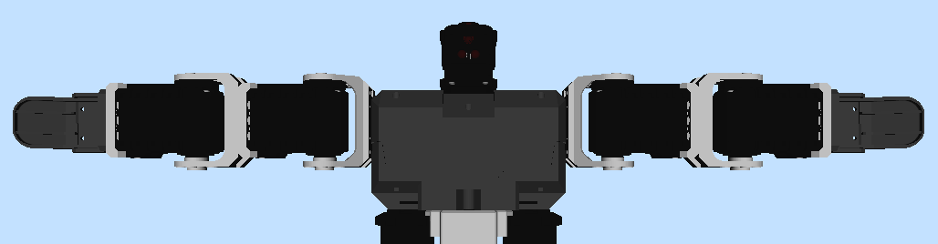
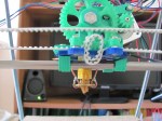
The x-axis carriage mounted onto its guiding rods.
Attaching the idler bearing to the x-end-idler was a straightforward. The M8x50 mm bolt was used as a suggested alternative in place of a plain threaded bolt.
Next, the x-axis carriage was attached to the guiding rods. The blue carriage you see above is missing its bushings (print hiccup), so they were printed separately and glued on. The timing belt clamps are the same as the ones on the y-axis belt.
Before the x-axis carriage is mounted onto the z-axis vertical smooth rods, the latter have to be inserted into the RepRap frame.
Z-axis assembly
A plumb-line helped to line up the rods with the bottom bar-clamps. The top rod-clamps were attached to the z-motor holders using M3x25 mm bolts and respective washers. The bolts were placed with shafts pointing outwards from the frame, to avoid interference with the motors which will sit next to them later on.

Close-up of Z-axis motor mount and attached vertical smooth rod.
In the next stage, the x-axis carriage and remaining motors will be attached to the RepRap frame!