With the mechanical part of the RepRap largely completed, the next step was to wire up the electronics.
I had underestimated the amount of wiring required for the printer, so I braided the wire before wrapping it around the printer’s frame in an attempt to keep it as neat as possible. The wires have to be kept away from many moving parts, hot points, etc. Keeping them isolated should also minimise any cross-talk noise between the large lengths of cable. However, as the printer is going to have to be disassembled, packed and moved in the near future, I haven’t fixed the wires up with cable-ties yet.
The Danguinololu successfully communicated motor and temperature signals so everything seems in order, except for the extruder motor which is behaving in an irrational manner and only intermittently accepting movement signals in one direction. Leaving this problem aside, I moved on to testing the heated extruder tip.
The heated tip temperature was incremented in steps up to 210 °C, while manually feeding some PLA plastic into the extruder. The plastic flows out of the tip effortlessly at around 200 °C, so things are looking positive for the extruder assembly! The remaining step is to calibrate a working motor to extrude plastic at the right speed for printing.
-

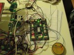
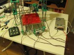
- Testing the electronics for the first time. The birdsnest of wires needs sorting out before the axes can be moved to their full range!
-
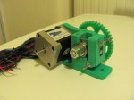
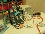
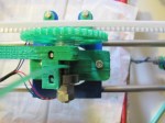
- A close-up of the Danguinololu in operation.
-
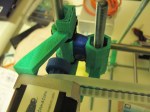
- The wires were tidied up by braiding, before wrapping them around the printer frame to keep them out of the way of moving parts.
-
- Labelling the wires helps greatly during the inevitable troubleshooting stage.
-

- Another close-up of the board and LED light show!
-

- The push-connectors are fairly hard to press down on, but guarantee a good contact and are much better than screw-based connectors.
-
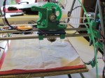
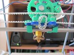
- First test of heating the extruder. The plastic flowed out the tip without pressure and with a good flow at around 200 °C.
-
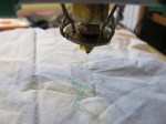
- Close-up of the working extruder. The plastic solidifies almost instantly once deposited.
-

- Another close-up of the working extruder.
-
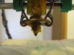
- Yet another close-up of the working extruder. The solder which reinforces the copper wire did not show signs of melting from the high temperatures, as it is futher away from the tip, with a large area exposed to the air.
-
- Top view of the working extruder, with plastic being manually fed through.
As I’m experiencing some issues with one of the motors, unfortunately the long-awaited calibration and test-printing stage has to wait!