
Some further progress on the RepRap build this weekend. The frame is now complete and awaiting electronics (sneak peek in the last picture)!
Main updates have been:
- The x-carriage plastic parts were reinforced with some Sugru as the vertical columns seemed weak and flexed with little force. The carriage was completed and mounted to the frame. The z-axis motors were attached to the top of the frame and connected to the x-carriage via the new-style couplings.
- The MDF wood top plate was attached to the bottom plate and can freely tilt via the corner springs. This allows the printing area to move under pressure, ensuring that the frame and extruder will not get damaged if the extruder happens to get lowered too far onto the print area. The heated bed (wired-up previously) was attached to the top wood plate, with all thermistor wiring tucked in-between.
- The extruder tip was attached to Wade’s extruder. Another strengthening mod here should ensure that the extruder PTFE barrier doesn’t get pushed out of the extruder by the force of incoming molten plastic, something which has happened with printer #1! The complete extruder assembly is now mounted on the x-carriage.
-

- X-carriage idler end with plastic bearings attached and some strength reinforcement mod for the weak vertical column.
-
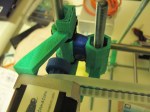
- X-carriage motor end with motor and timing belt installed. This plastic past also had its vertical column reinforced.
-

- Front view of extruder with motor and gear attached.
-
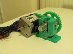
- Rear view of extruder with motor and gear attached.
-

- The only screws I had remaining for the Z-couplings were too long, so I sawed them down to size.
-

- The print bed assembly. The PCB heated bed sits above the two support plates (MDF wood). The heated bed and upper support plate can tilt freely via the corner springs.
-

- The completed extruder, with reinforcement mod on the brass barrel.
-
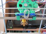
- The completed extruder mounted on the x-carriage.
-

- A closer view of the mounted extruder.
-

- First power-up test of the Danguinololu via USB.


